


下载

FN8091 Rev 3.00 Page 1 of 17
March 31, 2011
FN8091
Rev 3.00
March 31, 2011
ISL21400
Programmable Temperature Slope Voltage Reference
DATASHEET
The ISL21400 features a precision voltage reference
combined with a temperature sensor whose output voltage
varies linearly with temperature. The precision 1.20V
reference has a very low temperature coefficient (tempco),
and its output voltage is scaled by an internal DAC (V
REF
) to
produce a temperature stable output voltage that is
programmable from 0V to 1.20V. The output voltage from the
temperature sensor (V
TS
) is summed with V
REF
to produce
a temperature dependent output voltage.
The slope of the V
TS
portion of the output voltage can be
programmed to be positive or negative in the range
-2.1mV/°C to +2.1mV/°C. A programmable gain amplifier
(PGA) sums the V
TS
and the V
REF
voltages and provides
gains of 1x, 2x, and 4x to scale the output up to 4.8V and the
slope to ±8.4mV/°C.
The V
REF
and V
TS
terms are programmable with 8 bits of
resolution via an I
2
C bus and the values are stored in
non-volatile registers. The PGA gain is also set via the I
2
C
bus and the value is stored in a non-volatile register.
Non-volatile memory storage assures the programmed
settings are retained on power-down, eliminating the need
for software initialization at device power-up.
Temperature Characteristics Curve
Features
• Programmable reference voltage
• Programmable temperature slope
• Programmable Gain Amplifier
• Non-volatile storage of programming registers
•I
2
C serial interface
• 2% total accuracy over temperature and V
CC
range
• 200µA typical active supply current
• Operating temperature range = -40°C to +85°C
• 8 Ld MSOP package
• Pb-free (RoHS compliant)
Applications
• RF power amplifier bias compensation
• LCD bias compensation
• Laser diode bias compensation
• Sensor bias and linearization
• Data acquisition systems
• Variable DAC reference
• Amplifier biasing
Pinout
ISL21400
(8 LD MSOP)
TOP VIEW
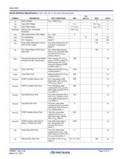
0.0
0.5
1.0
1.5
2.0
2.5
3.0
-40 -15 10 35 60 85
TEMPERATURE (°C)
V
REF
(V)
TS = 0
TS = 255
TS = 127
TS = 0
TS = 127
TS = 255
A
V
= 2
A
V
= 1
Pin Descriptions
MSOP SYMBOL DESCRIPTION
1 A2 Hardwire slave address pin for I
2
C serial bus
2 A1 Hardwire slave address pin for I
2
C serial bus
3 A0 Hardwire slave address pin for I
2
C serial bus
4V
SS
Ground pin
5 SCL Serial bus clock input
6 SDA Serial bus data input/output
7 VOUT Output voltage
8V
CC
Device power supply
A2
V
CC
1
2
3
4
SDA
SCL
8
7
6
5
A0
V
OUT
V
SS
A1
页面指南