


下载

1
TM
AN9925
1-888-INTERSIL or 321-724-7143
|
Intersil and Design is a trademark of Intersil Americas Inc.
Copyright © Intersil Americas Inc. 2001, All Rights Reserved
VRM8.5 Multiple-Output Motherboard Power
Controllers (ISL6523EVAL1, ISL6524EVAL1)
Introduction
Today’s high-performance desktop PC architectures
demand power solutions featuring increased integration
and reduced system-level costs. The Intersil ISL6523 and
ISL6524 are complex controllers that integrate two and
one, respectively, switching regulators, as well as two and
three, respectively, linear controllers in a single package.
The switching converters employ voltage-mode control
architecture and high circuit performance is insured by the
use of high gain-bandwidth product error amplifiers, high-
accuracy references, and continuously adaptive shoot-
through protection. The ICs offer a full range of protection
features including overcurrent, overvoltage, as well as fault
condition signaling and/or shutdown. All these combined
features makes them ideal for microprocessor point-of-use
power supply solutions. The ISL6523 and ISL6524 were
designed to provide most of the active-state power needs
of a typical Tualatin-based system. Some Coppermine-T
and Celeron-based systems may also benefit from the
ISL6523 or ISL6524. [1,2]
The ISL6523EVAL1 and ISL6524EVAL1 evaluation boards
embody 4-output regulator solutions targeted at supplying
power to the microprocessor core (1.05V - 1.825V), AGTL+
communication bus (1.2V), 4X AGP video (1.5V), and the
ICH/MCH chip set core (1.8V).
Evaluation Board Setup
Important!
The evaluation boards were not designed to support a
continuous V
CORE
output current in excess of 15A for
extended periods of time. When testing either board to
VOUT1 output currents in excess of 15A, restrict the ON time
to less than 2 minutes, followed by at least 4 minutes OFF.
To facilitate the evaluation of the ISL6523 or ISL6524 in a
typical setting, both evaluation boards were designed to be
powered primarily from an ATX power supply [3]. However,
the boards have hook-up turret terminals that allow them to
be powered from standard laboratory power supplies.
Circuit Setup
Before connecting an input supply to the board, consult the
circuit schematics and familiarize yourself with the various
connection options offered by either evaluation board.
➤
Set the Power-On Switch
Ensure the ‘ATX ON’ (SW2) switch is in the off position (lever
pointing away from ‘ATX ON’ marking).
➤
Set Core Voltage SW1
SW1, by means of the on-chip D/A converter, sets the output
voltage for the V
CORE
(VOUT1) output according to the
corresponding table detailed in the IC’s data sheet. Consult
the data sheet and set the status of the VID pins according
to the core output voltage level you wish to regulate to.
➤
Hookup Guide Using Standard Bench Supplies
Connect a 5V, 16A supply to the +5VIN input, a 3.3V, 6A,
supply to the +3.3VIN input, and a +12V, 100mA to the
+12VIN input. Using a small jumper wire, connect the +5VIN
and +5VSB inputs. Connect typical loads to all the evaluation
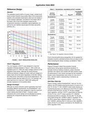
board’s outputs. Consult Table 1 for maximum loads
supported by the design of the board in the configuration
received; read the ‘Modifications’ section for information on
modifying either evaluation board to meet your special needs.
➤
Hookup Guide Using a Standard ATX Supply
Connect the 20-pin ATX connector to the on-board J1 mating
connector. Connect typical loads to all the evaluation board’s
outputs. Consult Table 1 for maximum loads supported by
the design of the board in the configuration received; read
the ‘Modifications’ section for information on modifying either
evaluation board to meet your special needs.
Operation
➤
Provide Power to the Board
Turn on the bench supplies. If using an ATX supply, plug it
into the mains, and if it has an AC switch, turn it on. The ‘ATX
OFF’ LED should light up, indicating the presence of 5V
standby on board. Flip on the ‘ATX ON’ switch and the ‘ATX
OFF’ LED should turn off. Shortly thereafter ‘VTT PGOOD’,
‘POWER GOOD’ and ‘ATX PGOOD’ LEDs should light up
indicating power good status on all the outputs, as well as
the input voltages provided by the ATX supply. If bench
supplies are used, the ‘ATX OFF’ LED will only report the
status of the SW2 switch, and the ‘ATX PGOOD’ LED will not
light up under any circumstance; the other indicators will
preserve their functionality.
➤
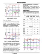
Examine Start-Up Waveforms / Output Quality Under
Varying Loads
Start-up is immediate following application of bias voltage.
Using an oscilloscope or other laboratory equipment, you may
study the ramp-up and/or regulation of the controlled voltages
under various loading conditions. For maximum versatility, we
recommend the use of a programmable electronic load.
Fault Handling
In case of a fault condition (output undervoltage on the linear
outputs, or overcurrent on the switching output), the entire IC
shuts down and undergoes a re-start attempt. Three
consecutive fault situations on any of the outputs (single fault
on VOUT4, 1.8V output) latch the chip off. Review the
appropriate data sheet section for more detail.
Application Note May 2001
Author: Bogdan M. Duduman