
下载
1
Application Note 1545
ISL62884CEVAL2Z Evaluation Board User Guide
Hardware Description
The ISL62884CEVAL2Z evaluation board demonstrates
the performance of the ISL62884C single-phase
synchronous-buck PWM V
CORE
controller implementing
Intel IMVP-6 protocol. The ISL62884C features Intersil's
Robust Ripple Regulator (R
3
™) technology. An on-board
dynamic-load generator is included for evaluating the
transient-load response. It applies a 300µs pulse of
approximately 0.25Ω load across V
O
and PGND.
Contents of this document include:
• Design Criteria
• Recommended Test Equipment
• Interface Connections
• Switch Descriptions
• DIP Switch Descriptions
• Jumper Descriptions
• Test Point Descriptions
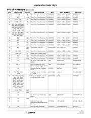
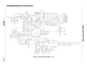
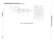
• Evaluation Board Documentation
- Bill of materials
-Schematic
- Silk-screen plots
-Board layer plots
Recommended Equipment
• (Qty. 1) Adjustable 25V, 10A Power Supply
• (Qty. 1) Fixed 5V, 100mA Power Supply
• (Qty. 1) Fixed 12V, 100mA Power Supply
• (Qty. 1) Adjustable Constant Current Electronic Load
• (Qty. 1) Digital Voltmeter
• (Qty. 1) Four-Channel Oscilloscope
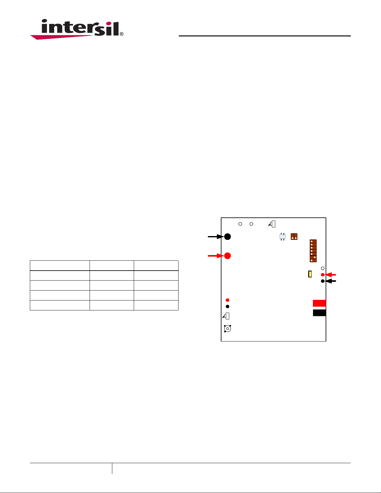
Interface Connections
•V
IN
: Input Voltage to the Power Stage
-J5: V
IN
Positive Power Input
- TP31: V
IN
Positive Voltage Sense
-J6: V
IN
Return Power Input
- TP32: V
IN
Return Voltage Sense
•V
O:
Regulated Output Voltage
-J12: V
O
Positive Power Output
-J14: V
O
Return Power Output
•+5V: +5V Input Voltage
- TP29: +5V Positive Input
- TP30: +5V Return Input
• +12V: Input Voltage for the Dynamic-load Generator
- TP3: 12V Positive Input
- TP2: 12V Return Input
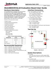
Test Set-Up
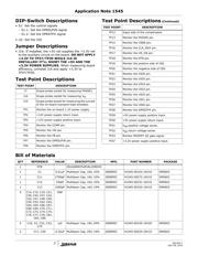
Switch Descriptions
•S3: Enable
- OFF: Short the VR_ON pin to GND (disable PWM)
- ON: Allow the VR_ON pin to pull-up to +5V (enable
PWM)
•S2: Dynamic Load
- OFF: On-board dynamic load disabled
- ON: On-board dynamic load enabled
TABLE 1. DC/DC DESIGN CRITERIA
PARAMETER VALUE UNITS
V
IN
4.5 to 20 VDC
V
O
0 to 1.5 VDC
Full-load 60 ADC
PWM Frequency 300 kHz
10
U2
ISL62884CEVAL2Z
on
off
0
1
TP37
TP29
TP30
VID0
VID1
VID2
VID3
VID4
VID5
VID6
Vin
+
_
TP18 TP14
VSENRTN
J10
VCORE
on
off
S3
S2
TP3
TP2
5V
+
_
J12
VCORE
J14
PGND
S1
DPRSLPVR
+3.3V
+5V
PGND
J6
PGND
J5
VIN
D1
J16
DPRSTP#
FIGURE 1. TEST SET-UP
CAUTION: These devices are sensitive to electrostatic discharge; follow proper IC Handling Procedures.
1-888-INTERSIL or 1-888-468-3774
| Intersil (and design) is a registered trademark of Intersil Americas Inc.
Copyright Intersil Americas Inc. 2010. All Rights Reserved
All other trademarks mentioned are the property of their respective owners.
April 28, 2010
AN1545.1
Author: Jia Wei