


下载
1
TM
AN9908.2
Pentium® is a registered trademark of Intel Corporation.
1-888-INTERSIL or 321-724-7143 | Intersil and Design is a trademark of Intersil Americas Inc.
Copyright © Intersil Americas Inc. 2001, All Rights Reserved
Peripheral Power Controller for Pentium® 4
Computer Systems (HIP6521EVAL1)
Introduction
The progress of the advanced computing cores coming from
microprocessor manufacturers such as Intel and AMD have
necessitated a change in the topology of the switching
regulators traditionally used to power these processor cores.
Multiphase buck regulators have proven to be the topology
of choice for such high-current applications. However, the
distributed power system architecture of these computers
continue to have a need for other sub-system specific
voltages. The HIP6521 was created to complement a
multiphase buck controller in creating a complete power
solution for the typical Pentium 4 system. Athlon-class
processor based systems (AMD) may also benefit from the
HIP6521. [1]
The HIP6521EVAL1 evaluation board embodies a 4-output
regulator solution targeted at supplying power to the system
memory (2.5V), system clock (2.5V), ICH/MCH chip set core
(1.8V), and the 4X AGP video (1.5V), with provisions for
ACPI power management implementation. [2]
Quick Start Evaluation
Important!
To facilitate the evaluationof the HIP6521 in atypical setting,
the HIP6521EVAL1 was designed to be powered primarily
from an ATX supply. However, the board does have hook-up
turret terminals that allow it to be piggy-backed in an actual
computer system, or be powered from standard laboratory
power supplies
If an ATX power supply is used to power the board (using the
on-board 20-pin connector), remember that regulation of
most ATX supplies is generally dependent on the presence
of a DC load on the main 5V output. Therefore, for best
results, have a 5Ω/25W-50W power resistor connected to
the 5V output of the ATX supply (take necessary
precautions, as the resistor may get very hot). [3]
Circuit Setup
Before connecting an input supply to the board, consult the
circuit schematic and familiarize yourself with the various
connection options offered by the HIP6521EVAL1.
➤ Set Switches
Ensure the ‘ATX ON’ (SW1) switch is in the off position
(away from ‘ATX ON’ marking) and ‘S3/S5’ (SW2) switch is
in the middle position (away from ‘S3’ or ‘S5’ marking).
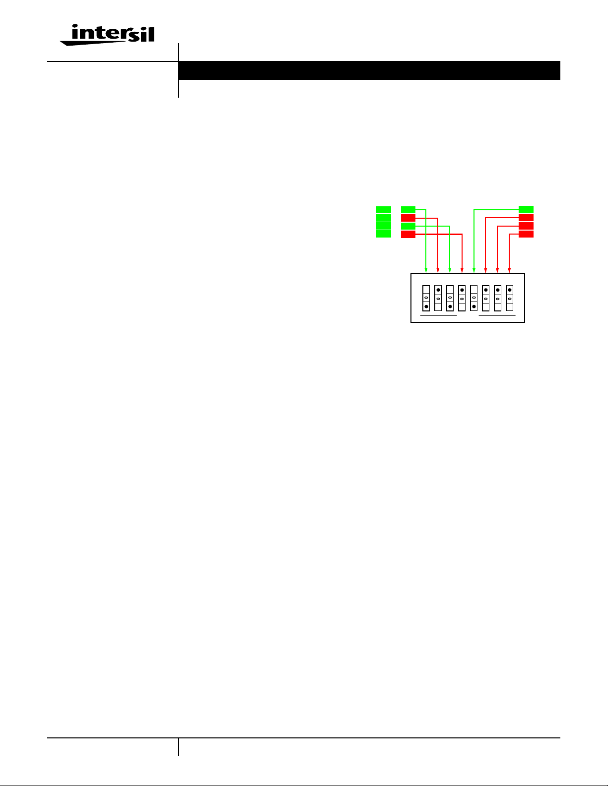
SW3 helps with the control of the various outputs in ACPI
shutdown states. To avoid having the powerful output drives
(of the regulators that have to be off in certain sleep states)
hold the outputs within regulation, they have to be actively
kept off by pulling the corresponding FB pins above 1.25V.
Each output can thus be turned off or kept running in S3
and/or S5 states, with corresponding consequences. For
initial evaluation, we recommend closing positions 2, 4, and
6-8 (see Figure 1 for detail). Unless otherwise specified, this
recommended SW3 configuration was employed throughout
testing of the board described in this application note.
➤ Set Jumpers JP1-4
JP1 and JP3 select the on-board input voltage for the linear
pass elements corresponding to the VOUT3 and VOUT4
outputs, respectively. One recommended configuration for
initial evaluation is with JP1 populated in the ‘2.5VIN’
position and JP3 in the ‘3.3VIN’ position.
JP2 and JP4 select the ‘+3.3VDUAL’ as the input for the two
linear pass elements mentioned above. If an external
3.3VDUAL source is supplied, either pass element (Q4 and/or
Q5) maybe poweredfrom this sourceby moving the respective
header jumper from JP1 or JP3, onto JP2 or JP4, respectively.
➤ Hookup Guide Using Standard Bench Supplies
Connect a 5V, 16A supply to the +5VDUAL input and a 3.3V,
4A, supply to the +3.3VIN input. Another 3.3V, 4A supply may
be needed for the optional +3.3VDUAL input if either JP2 or
JP4 are populated. Connect typical loads to all the evaluation
board’s outputs. Consult Table 1 for maximum loads
supported by the design of the in the configuration received;
consult the ‘Modifications’ section forinformation onmodifying
the evaluation board to meet your special needs.
➤ Hookup Guide Using a Standard ATX Supply
Connect the 20-pin ATXconnector to the on-board J1mating
connector. Connect typical loads to all the evaluation board’s
outputs. Consult Table 1 for maximum loads supported by
the design of the in the configuration received; consult the
‘Modifications’ section for information on modifying the
evaluation board to meet your special needs.
FIGURE 1. SW3 DETAIL (RECOMMENDED INITIAL
CONFIGURATION) - SLEEP STATES SUPPORT
OPEN
1
2
3
4
5
6
7
8
VOUT1
S0
S3
S5
VOUT2
VOUT3
VOUT4
ON
ON
ON
ON
OFF
ON
ON
OFF
OFF
OFF
OFF
ON
Application Note March 2001
Author: Bogdan M. Duduman