

下载
1
Application Note 1896
Author: Richard Garcia
HIP2103, HIP2104 Evaluation Board User’s Guide
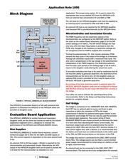
Introduction
The HIP2103_4MBEVAL1Z is an evaluation tool for the
HIP2103 and HIP2104 half bridge MOSFET drivers. This tool
consists of a mother board and HIP2103DBEVAL1Z and
HIP2104DBEVAL1Z evaluation daughter cards. The mother
board platform provides an on-board microcontroller that is
used to generate appropriate control inputs to the HIP2103 or
HIP2104. The frequency, the PWM duty cycle, and the dead-time
provided by the microcontroller are user adjustable.
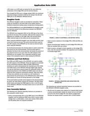
For customers who desire to provide their own external signals,
the on-board controller can be configured to allow the
daughter cards to be controlled by externally provided inputs.
The daughter cards can also be used as stand-alone units
mounted on a customer designed main board that
incorporates customer selected bridge FETs and any other
external circuits desired. The daughter cards have optional
circuits so that the HIP2103 or HIP2104 can be configured as
required by the customer’s application.
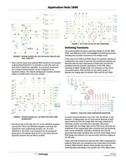
Scope
This application note covers the use of the HIP2103_4 mother
board and the HIP2103_4 daughter cards. Details for setting
up and using the microcontroller are covered. Assembly
options on the motherboard are also reviewed. Sample
waveforms are also provided.
The microcontroller firmware is provided on request but the
only support offered by Intersil will be for bug corrections.
Please refer to Microchip for details on the use of the
PIC18F2431.
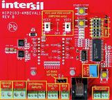
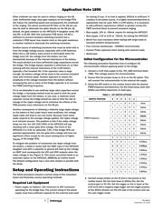
Physical Layout
The HIP2103_4MBEVAL1Z board is 84mm by 94mm. The
tallest component is the RJ25 connector. The total height is
38mm. Multiple inputs have miniature terminal blocks and the
high current battery inputs and load outputs have larger
terminal blocks rated for 15A each connection. Three
push-buttons are used for RESET, START/STOP, and SLEEP
functions. An on-board potentiometer is used to adjust the
duty cycle.
The 6 position DIP switch is used to setup the PWM switching
frequency (positions 1, 2, and 3) and the dead-time (positions
4, 5, and 6). One specific combination of DIP switch settings
(all positions set to on) disables the signals from the
microcontroller and enables all of the external inputs.
For those customers who would like to modify the firmware of
the PIC18F2431 microcontroller, an RJ25 connector is
provided for easy connection with Microchip firmware
development tools (not provided or supported by Intersil).
Specifications
Bridge Bias Voltage (V
BAT
) 5V minimum, 50V maximum
operating including transients
External Bias for Microcontroller 3.3V - 5.0V, ~30mA
Maximum Bridge Current 20A
PWM Switching Frequency 5kHz to 40kHz in 5kHz increments
PWM Duty Cycle adjustable from 0% to ~ 98%
Dead-time 0.0µs to 2.8µs in 400ns increments
Large Terminal Blocks 15A each connection
Small Terminal Blocks 6A each connection
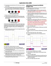
FIGURE 1. HIP2103_4MBEVAL1Z, FRONT AND BACK VIEWS
FREQ
DEAD
TIME
DUTY
CYCLE
BRIDGE
BIAS
LOAD
EXTERNAL
INPUTS
Vdd, Vcc
I/O
BIAS
uC
Not used
uC BIAS
OPTION
VCC and VDD on/off
(HIP2104 only)
Observe the
installation
polarity
November 13, 2013
AN1896.0
CAUTION: These devices are sensitive to electrostatic discharge; follow proper IC Handling Procedures.
1-888-INTERSIL or 1-888-468-3774
| Copyright Intersil Americas LLC 2013. All Rights Reserved
Intersil (and design) is a trademark owned by Intersil Corporation or one of its subsidiaries.
All other trademarks mentioned are the property of their respective owners.