

下载

Maxim > Design Support > Technical Documents > Application Notes > Digital Potentiometers > APP 4110
Maxim > Design Support > Technical Documents > Application Notes > Optoelectronics > APP 4110
Keywords: DS1865,burst-mode, PON, PON controller, passive optical network, APC, automatic power
control
APPLICATION NOTE 4110
DS1865 Quick Reference Guide
By: Hrishikesh Shinde
Sep 27, 2007
Abstract: The DS1865 burst-mode PON controller with integrated monitoring provides programming
options required to configure the alarms, warnings, lookup tables, and other functions detailed in
Application Note 4052, Quick Reference Guide to the DS1863 Memory Map. This programmability
necessitates a large register memory map. This application note provides an alternate outline of the
register map, which is convenient when programming the device.
Introduction
The DS1865 is a burst-mode PON controller with integrated monitoring capabilities. It features seven
separate memory tables that are internally organized into eight byte rows. In addition this controller has
auxiliary memory, which is EEPROM accessible at the A0h slave address.
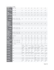
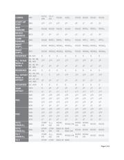
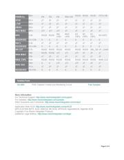
Memory Map of the DS1865
The Lower Memory is addressed from 00h to 7Fh. This memory contains alarm and warning thresholds,
flags, masks, several control registers, password entry area (PWE), and the Table Select byte. See
Figure 1.
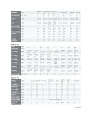
Table 01h primarily contains EEPROM (with PW1-level access) and some alarm and warning status
bytes.
Table 02h is a multifunction space that contains configuration registers, scaling and offset values,
passwords, interrupt registers, and other miscellaneous control bytes.
Table 03h is strictly EEPROM that is protected by a PW2-level password.
Table 04h contains a temperature-indexed lookup table (LUT) for controlling the modulation voltage. The
modulation LUT can be programmed in 2°C increments over the -40°C to +102°C range. Access to this
LUT is protected by a PW2-level password.
Table 05h contains another LUT which allows the APC set point to change as a function of temperature
to compensate for Tracking Error (TE). The TE LUT has 36 entries that determine the APC setting in 4°C
windows between -40°C to +100°C. Access to this LUT is protected by a PW2-level password.
Page 1 of 6