
下载
UG-CPC5621-EVAL-RDL/CPC5621-EVAL-CDL-R2.0 www.clare.com 1
1. Introduction
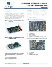
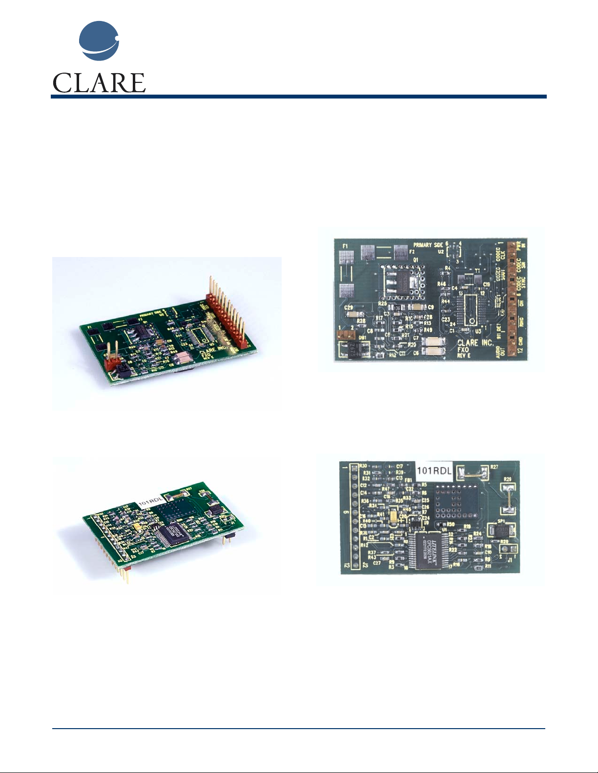
Thank you for using this Clare LITELINK III evaluation
board. LITELINK III evaluation boards ship with
CPC5621 full-wave ring detection LITELINK III parts
and in one of two configurations; resistive AC termina-
tion circuit (CPC5621-EVAL-RDL) or reactive AC ter-
mination circuit (CPC5621-EVAL-CDL).
Figure 1. LITELINK III Evaluation Board, Primary
(Top) View
Figure 2. LITELINK III Evaluation Board, Second-
ary (Bottom) View
Use the three-letter code on the label on the printed-
circuit board to determine the AC termination you
have.
• CDL = reactive AC termination
• RDL = resistive AC termination
NOTE: The printed-circuit board used for LITELINK III
evaluation boards is a multi-purpose board. It includes
many stuff options and circuits not used when manu-
factured as a LITELINK III evaluation board. For more
information, see Stuffing Options on page 2.
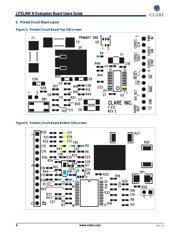
1.1 Component Locations
Figure 3. Primary (Top) Side Components
1. CPC5602C FET
2. Bridge Rectifier
3. Snoop Capacitors
4. CODEC area (not stuffed for evaluation board)
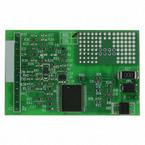
Figure 4. Secondary (Bottom) Side Components
5. FET Heatsink
6. LITELINK
7. Sidactor Circuit Protector
CPC5621-EVAL-RDL/CPC5621-EVAL-CDL
LITELINK™ III Evaluation Board
User’s Guide