
下载
Product
Folder
Sample &
Buy
Technical
Documents
Tools &
Software
Support &
Community
Reference
Design
CC2620
SWRS178A –FEBRUARY 2015–REVISED DECEMBER 2015
CC2620 SimpleLink™ ZigBee
®
RF4CE Wireless MCU
1 Device Overview
1.1 Features
1
– Very Few External Components
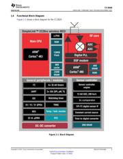
• Microcontroller
– Seamless Integration With the SimpleLink™
– Powerful ARM
®
Cortex
®
-M3
CC2590 and CC2592 Range Extenders
– EEMBC CoreMark
®
Score: 142
• Low Power
– Up to 48-MHz Clock Speed
– Wide Supply Voltage Range
– 128KB of In-System Programmable Flash
• Normal Operation: 1.8 to 3.8 V
– 8KB of SRAM for Cache
• External Regulator Mode: 1.7 to 1.95 V
– 20KB of Ultralow-Leakage SRAM
– Active-Mode RX: 5.9 mA
– 2-Pin cJTAG and JTAG Debugging
– Active-Mode TX at 0 dBm: 6.1 mA
– Supports Over-The-Air Upgrade (OTA)
– Active-Mode TX at +5 dBm: 9.1 mA
• Ultralow-Power Sensor Controller
– Active-Mode MCU: 61 µA/MHz
– Can Run Autonomous From the Rest of the
– Active-Mode MCU: 48.5 CoreMark/mA
System
– Active-Mode Sensor Controller: 8.2 µA/MHz
– 16-Bit Architecture
– Standby: 1 µA (RTC Running and RAM/CPU
– 2KB of Ultralow-Leakage SRAM for Code and
Retention)
Data
– Shutdown: 100 nA (Wake Up on External
• Efficient Code Size Architecture, Placing Drivers,
Events)
IEEE 802.15.4 MAC, and Bootloader in ROM
• RF Section
• RoHS-Compliant Packages
– 2.4-GHz RF Transceiver Compatible With IEEE
– 4-mm × 4-mm RSM VQFN32 (10 GPIOs)
802.15.4 PHY and MAC
– 7-mm × 7-mm RGZ VQFN48 (31 GPIOs)
– Excellent Receiver Sensitivity (–100 dBm),
• Peripherals
Selectivity, and Blocking Performance
– All Digital Peripheral Pins Can Be Routed to
– Link budget of 105 dB
Any GPIO
– Programmable Output Power up to +5 dBm
– Four General-Purpose Timer Modules
– Single-Ended or Differential RF Interface
(Eight 16-Bit or Four 32-Bit Timers, PWM Each)
– Suitable for Systems Targeting Compliance With
– 12-Bit ADC, 200-ksamples/s, 8-Channel Analog
Worldwide Radio Frequency Regulations
MUX
• ETSI EN 300 328 (Europe)
– Continuous Time Comparator
• EN 300 440 Class 2 (Europe)
– Ultralow-Power Analog Comparator
• FCC CFR47 Part 15 (US)
– Programmable Current Source
• ARIB STD-T66 (Japan)
– UART
• Tools and Development Environment
– 2× SSI (SPI, MICROWIRE, TI)
– Full-Feature and Low-Cost Development Kits
– I2C
– Multiple Reference Designs for Different RF
– I2S
Configurations
– Real-Time Clock (RTC)
– Packet Sniffer PC Software
– AES-128 Security Module
– Sensor Controller Studio
– True Random Number Generator (TRNG)
– RemoTI™ Target Emulator
– 10, 15, or 31 GPIOs, Depending on Package
– SmartRF™ Studio
Option
– SmartRF Flash Programmer 2
– Support for Eight Capacitive-Sensing Buttons
– IAR Embedded Workbench
®
for ARM
– Integrated Temperature Sensor
– Code Composer Studio™
• External System
– On-Chip internal DC-DC Converter
1
An IMPORTANT NOTICE at the end of this data sheet addresses availability, warranty, changes, use in safety-critical applications,
intellectual property matters and other important disclaimers. PRODUCTION DATA.