

下载

1
AT89C51RC2 FLIP Programming Guide
In order to program the AT89C51RC2 using FLIP, the processor needs to execute the on-chip
bootloader code. The bootloader can be activated by two methods (hardware conditions or
regular boot process), as explained on page 93 of the AT89C51RC2 data sheet and in the Atmel
application note "C51 General Information about Bootloader and in System Programming".
In order to execute the bootloader using hardware conditions, the /EA pin must be high and the
/PSEN pin must be low at the falling edge of the reset signal. /PSEN must be released after the
falling edge of the reset signal, since /PSEN is normally an output that is driven by the processor.
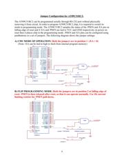
/EA = 1 and /PSEN = 0 at the falling edge of reset
One could accomplish these hardware conditions by the following:
1. Configure /EA to be a logic high, perhaps by using a jumper.
2. Press and hold the reset pushbutton.
3. Press and hold a pushbutton that connects /PSEN to ground through a 1K resistor.
4. Release the reset pushbutton (while still holding the /PSEN pushbutton).
5. Release the /PSEN pushbutton. The processor should now be in bootloader mode.
6. Configure /EA as necessary for the user application (either high or low). To execute user
code that is stored in the on-chip flash, /EA will remain high.
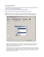
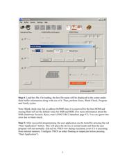
This configuration will forcibly place the AT89C51RC2 in serial programming mode. After
reset, the Flip software can be started or set up for RS-232 communication and will connect to
the bootloader in the processor.
Hardware changes required: (Refer to jumper configuration of AT89C51RC2)
1. Connect a three-pin header and jumper to allow the /EA pin to be configured as high or
low.
2. Connect a pushbutton switch or three-pin header and jumper to allow the /PSEN pin to be
configured as low or to allow it to toggle as an output pin under normal operation. Use a
1K current limiting resistor.