


下载

User's Guide
SLAU147 – January 2005
ADS1601/02 EVM User's Guide
This user’s guide describes the characteristics, operation, and use of the ADS1601/02
EVM 16-bit analog-to-digital evaluation board. A complete circuit description, a
schematic diagram, and a bill of materials are included.
Contents
1 Related Documentation from Texas Instruments ............................................... 2
2 EVM Overview ...................................................................................... 2
3 Analog Interface .................................................................................... 6
4 Digital Interface ..................................................................................... 9
5 Power Distribution ................................................................................. 11
6 Getting the Most From Your EVM .............................................................. 12
Appendix A ADS1601/ADS1602EVM Bill of Materials ............................................ 19
Appendix B ADS1601/02 Schematic ................................................................ 21
Appendix C ADS1601/02 EVM Layout Details ..................................................... 22
List of Figures
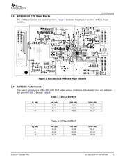
1 ADS1601/02 EVM Board Major Sections ....................................................... 3
2 FFT Plot, -1 dB, Internal Reference .............................................................. 5
3 FFT Plot, -1 dB, External Reference ............................................................ 5
4 FFT Plot, -6 dB, Internal Reference .............................................................. 5
5 FFT Plot, -6 dB, External Reference ............................................................. 5
6 FFT Plot, -10 dB, Internal Reference ............................................................ 5
7 FFT Plot, -10 dB, External Reference ........................................................... 5
8 Board Stack-Up ..................................................................................... 6
9 Single-Ended Via SMA Connector ............................................................... 7
10 Reference Voltage Block Diagram ............................................................... 8
11 ADS1601/02 Serial Control Signals ............................................................ 10
12 Control Signal Routing ........................................................................... 10
13 5-6K Interface Board Options for TI DSK ...................................................... 12
14 Jumper Settings for J13 and J14 on 5-6K Interface Board .................................. 13
15 CCS Project Menu ................................................................................ 14
16 CCS Project Open Dialog ........................................................................ 15
17 CCS Project View ................................................................................. 15
18 CCS Context Menu ............................................................................... 16
19 CCS Graph Property Window ................................................................... 17
20 CCS Window with Graph ......................................................................... 18
C-1 Top Tracking Layer ............................................................................... 22
C-2 Internal Power Layer .............................................................................. 22
C-3 Internal Ground Layer ............................................................................ 23
C-4 Bottom Tracking Layer ........................................................................... 23
List of Tables
1 EXTCLK/EXTREF .................................................................................. 3
2 EXTCLK/INTREF ................................................................................... 3
ADS1601/02 EVM User's GuideSLAU147 – January 2005 1