


下载

ADRF6520-EVALZ User Guide
UG-1045
One Technology Way • P. O. Box 9106 • Norwood, MA 02062-9106, U.S.A. • Tel: 781.329.4700 • Fax: 781.461.3113 • www.analog.com
Evaluating the ADRF6520 Dual-Channel, Programmable Low-Pass Filters and VGAs,
for 2 GHz Channel Spacing for Microwave Radios
Rev. 0 | Page 1 of 14
FEATURES
Standard single-ended interfacing
Differential interfacing available
Supply voltage easily applied to test loops
Analog gain control applied to test loops
VRMS output via SMA or 2-pin header
SPI signals available via the P3 header
EVALUATION KIT CONTENTS
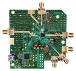
ADRF6520-EVALZ evaluation board
EQUIPMENT NEEDED
6 GHz signal generator
6 GHz spectrum analyzer
3-channel power supply that can supply 600 mA on at least
1 channel
SDP-S controller board
PC
DMM/voltmeter
VNA
DOCUMENTS NEEDED
ADRF6520 data sheet
SOFTWARE NEEDED
ADRF6520 Evaluation Software
GENERAL DESCRIPTION
This user guide describes the ADRF6520-EVA L Z evaluation
board kit for the ADRF6520 dual-channel, programmable, low-
pass filters and variable gain amplifiers (VGAs) and how to
configure the evaluation board to evaluate the ADRF6520 in a
single-ended or differential configuration.
The ADRF6520 features a filter bypass mode that extends the
bandwidth greater than 1 GHz. The ADRF6520-EVA L Z
evaluation board allows the user to test all the functions and
features offered by the ADRF6520 including low-pass filtering,
analog gain control, and the on-chip rms detectors. Signal path
traces are matched and are intuitively laid out on the left and
right side of the evaluation board, providing easy interfacing
with other evaluation boards.
The ADRF6520-EVA LZ uses an SDP-S controller board to
program its signal peripheral interface (SPI) port using the
ADRF6520 Evaluation Software.
A full description and complete specifications for the ADRF6520
are provided in the ADRF6520 data sheet and should be consulted
in conjunction with this user guide when using the
evaluation board.