
下载
ADP8860 Parallel Backlight Driver with ALS
Evaluation Board Manual
EVAL-ADP8860
Rev. 0
Evaluation boards are only intended for device evaluation and not for production purposes.
Evaluation boards are supplied “as is” and without warranties of any kind, express, implied, or
statutory including, but not limited to, any implied warranty of merchantability or fitness for a
particular purpose. No license is granted by implication or otherwise under any patents or other
intellectual property by application or use of evaluation boards. Information furnished by Analog
Devices is believed to be accurate and reliable. However, no responsibility is assumed by Analog
Devices for its use, nor for any infringements of patents or other rights of third parties that may result
from its use. Analog Devices reserves the right to change devices or specifications at any time
without notice. Trademarks and registered trademarks are the property of their respective owners.
Evaluation boards are not authorized to be used in life support devices or systems.
One Technology Way, P.O. Box 9106, Norwood, MA 02062-9106, U.S.A.
Tel: 781.329.4700
www.analog.com
Fax: 781.461.3113 ©2009 Analog Devices, Inc. All rights reserved.
FEATURES
Input voltage: 2.3 V to 5.5 V
Evaluates backlight, individual sinks, and dual light sensing
Translates USB to I
2
C interface
Jumpers for measurement of the LEDs and input supply current
On-board reset push-button and interrupt indicator
Connector to interface external target hardware
On-board regulators
Individually selectable on-board LEDs for backlight and
keypad light
GENERAL DESCRIPTION
The evaluation system is composed of a motherboard and
a daughterboard. The motherboard provides the I
2
C® signals
from the computer USB port and generates the I/O voltages
and digital high and low signals for the daughterboard.
The motherboard features a 3.3 V regulator (VBOARD), a 3.7 V
regulator (VBATT), and a 2.7 V regulator (VDDIO). VBOARD
is the motherboard logic supply whereas VBATT provides
power to the daughterboard. VDDIO is the digital I/O voltage
supplying the I
2
C interface and the control pins. Jumper LK1 to
Jumper LK3 on the motherboard define whether the internal
regulators input voltage is supplied from the USB port or from
external supplies connected to J29. The motherboard regulators
are powered from the USB-VBUS line when Jumper LK1 to
Jumper LK3 are in the USB position. External voltages can be
applied to J29 to supply the motherboard and daughterboard,
Jumpers LK1 to LK2 must be set to EXT position to use the
external supply option.
The daughterboard contains numerous jumpers, LEDs, and test
points for easy evaluation and monitoring of the board.
EVALUATION KIT CONTENTS
ADP8860 evaluation board
ADP8860 daughterboard
USB cable
Evaluation software
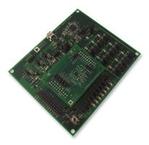
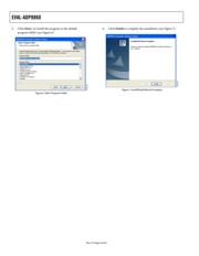
MOTHERBOARD AND DAUGHTERBOARD LAYOUT
07988-001
Figure 1.