
下载
APPLICATION NOTE
1
AN202
USB UART BOARD DESIGN CONSIDERATIONS FOR USB COMPLIANCE
1.0 INTRODUCTION
The XR21V1410, XR21V1412 and XR21V1414 USB UARTs have passed compliance for USB 2.0 Full-Speed
and are listed on the USB-IF Integrator’s List. This application note describes some scenarios to consider
when designing a commercial product using the XR21V141x to ensure that it has a higher possibility of
passing USB compliance.
2.0 DESIGN CONSIDERATIONS
The first design option to consider is whether the commercial product will be a self-powered or bus-powered
design.
In a self-powered design, an alternative power source is supplied via a power jack or battery to the USB UART
and other components on the board (See
Figure 1). Design considerations for a self-powered design are
discussed in Section 2.1.
In a bus-powered design, the 5V from the VBUS of the USB connector (from the USB host) provides power
source for the USB UART and possibly other components on the board (See
Figure 2). Design considerations
for a bus-powered design are discussed in Section 2.2.
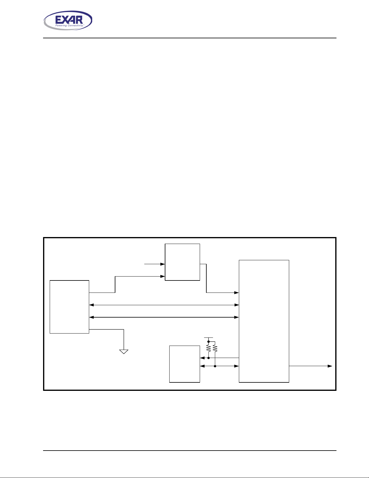
2.1 Design Considerations for Self-Powered Applications
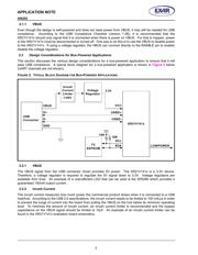
This section discusses the various design considerations for a self-powered application to ensure that it will
pass USB compliance. A typical block diagram for a self-powered application is shown in
Figure 1 below
(UART channels are not shown).
FIGURE 1. TYPICAL BLOCK DIAGRAM FOR SELF-POWERED APPLICATIONS
XR21V141x
VBUS
D+
D-
GND
USB
Connector
USBD+
USBD-
VCC
Voltage
Regulator
I
2
C
EEPROM
SCL
SDA LOWPOWER
3.3V
EN
External 5V
VCC
10K
10K