
下载
APPLICATION NOTE
1
AN204
UART SLEEP MODE
1.0 INTRODUCTION
This application note describes the general issues about sleep mode of UARTs. Sleep mode is for reducing
power consumption when UARTs are not actively used.
2.0 ENTERING SLEEP MODE
When the UART is not actively used, the sleep mode can be enabled to minimize power consumption. In the
sleep mode, the UART stops its clock oscillator to conserve power.
2.1 CONDITIONS TO ENTER THE SLEEP MODE
Generally, all the following conditions must be satisfied for the UART to enter the sleep mode:
• no interrupts pending (ISR bit-0 = 1)
• modem inputs are not toggling (MSR bits 0-3 = 0)
• RX input pin is idling HIGH
• divisor (the value in DLL register) is non-zero
• TX and RX FIFOs are empty
2.2 INITIALIZATION FOR ENABLING THE SLEEP MODE
If the sleep mode bit is located in IER bit-4, the documentation may refer to the following steps to enable the
sleep mode.
• LCR = 0xBF
• EFR[4] = 1
• LCR[7] = 0
• IER[4] = 1
If the sleep mode bit is located in sleep mode register (such as in PCI UARTs), we may refer to the following
steps to enable the sleep mode:
• Set SLEEP register to 0xFF (the maximum channel number is 8)
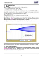
2.3 VERIFYING THE SLEEP MODE
The UART has entered the sleep mode when there is no clock on XTAL2 pin. If UART doesn’t go to sleep, then
one or more conditions have not been met. All the conditions in 2.1 need to be re-checked as well as make
sure that sleep mode has been enabled.
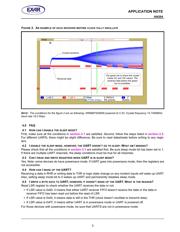
In any case, the sleep mode will not be entered while an interrupt is pending from any channel. The UART will
stay in the sleep mode of operation until it is disabled by setting sleep mode bit to a logic 0.
Also, it is recommended the RX pin is idling HIGH or “marking” condition during sleep mode. This may not oc-
cur when the external interface transceivers (RS-232, RS-485 or another type) are also put to sleep mode and
cannot maintain the “marking” condition. To avoid this, the system design engineer can use a 47k ohm pull-up
resistor on each of the RX input.