
下载
MLX Trim&Form guide SIP Hall sensors short form -- Rev 3.1 osa / 15-03-2008, p 1/4
Application of SIP Hall Sensors
Lead trimming and forming recommendations
Lead trim & form operations are often applied on SIP packaged Hall sensor ICs during system
assembly, in order to position the sensor exactly at operating position and shape the leads to secure
electrical contacts by soldering on PCB or welding.
Significant forces are applied during trim and form operations. Without appropriate precautions
applied force may act as a stress factor to the plastic body of the sensor or to the leads relative to the
plastic body. Such stress may cause a device malfunction, kay parameter drift or introduce a
reliability risk (latent defect), like below:
- Stress applied on the branded side of the package may cause Hall element parameter drift or
silicone structure damage.
- Stress applied on the leads relative to plastic body may cause wire bond damage, package
crack or delamination from a leadframe. Cracks and delamination, if not leading to an
immediate malfunction, will further weaken wire bonds, allow moisture penetration and
bond corrosion – all reliability risks.
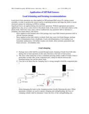
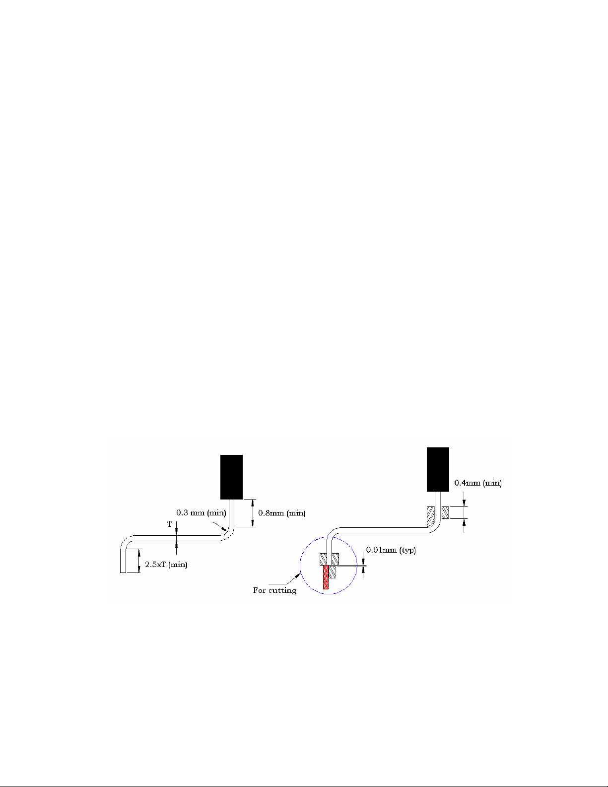
Lead clamping
Package stress relief shall be secured through steady clamping of leads from both sides
during trim or form operation (in the same direction as the trim or form action).
The stress relief clamp has to have a minimum pressing surface width of 0.4mm (1mm is
preferable) on both sides of the component pins, clamp lin shall be between the
bending(cutting) line and the plastic body.
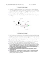
Care has to be taken that the clamping force is strong enough to hold the component pins
i
n
p
l
a
c
e
b
u
t
w
ithout damaging the leads on the clamping position (locally flattening the pins). When
pneumatic cylinders are used to operate clamping and cutting/bending, the force of
clamping cylinder shall be minimum 3 times the force of the cutting/bending one.