

下载
DN-111
Design Note
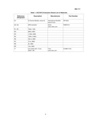
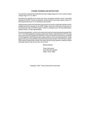
The UCC3973 demo board is a DC/AC inverter
module used to drive a cold cathode fluorescent
lamp (CCFL) typically used as the back-light
source for the LCD panel in a notebook computer.
The principle of operation for the inverter is ex
-
plained in the applications section of the
UCC3972/73 data sheet and will not be repeated
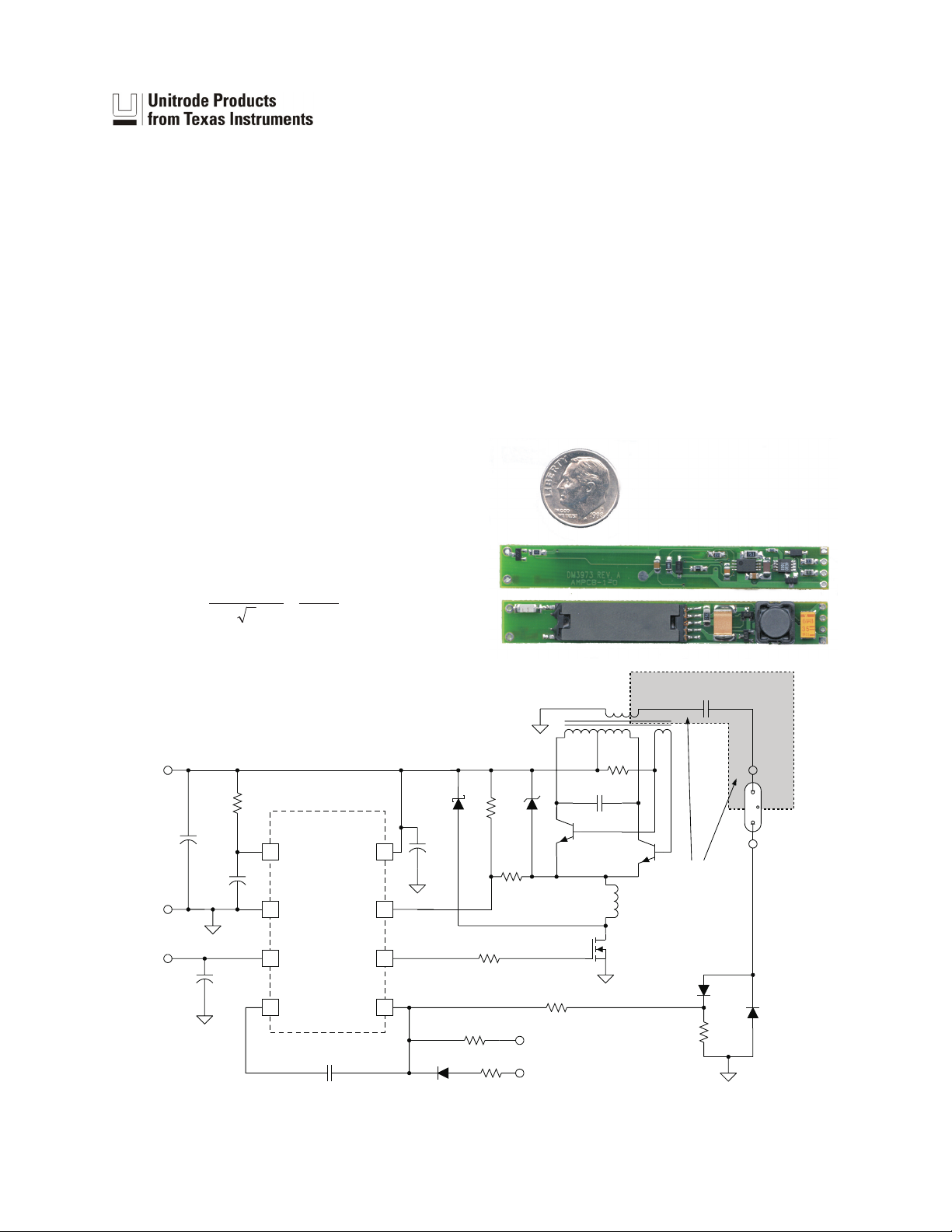
here. A complete schematic for the demo board is
given in Fig. 1 and a parts list is provided in
Table 1. As explained in the text that follows, the
evaluation board components can be easily modi
-
fied depending on the application requirements.
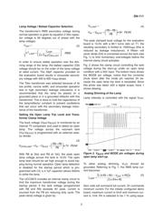
Transformer Selection / Lamp Striking Voltage
The voltage available to strike the lamp is a func-
tion of the minimum DC input voltage and the turns
ratio of T1.
()
V
V
N
N
RMS
STRIKE
IN
SEC
PRI
=
•
•
π
min
2
(1)
The transformer provided on the board (Toko
912MN-1016) has an 80:1 turns ratio, relating the
entire secondary turns to the primary. An 8V mini
-
mum input should provide 1400V
RMS
to strike the
lamp. Due to transformer’s leakage, however, the
actual voltage is only 1250V
RMS
. If a higher striking
voltage is required for the lamp an increased trans
-
former turns ratio, lower leakage transformer, or
higher minimum input voltage is necessary.
SLUA238A - MARCH 2000
UCC3973 Evaluation Board Design Note
1
3
2
4
UCC3973
7
6
8
5
VDD
GND
MODE
COMP FB
OUT
BUCK
VBAT
C4
33nF
R7
75
Q1
R8
2k
R9
1k
Q2
C5
0.15µF
Q3
R2 750
T1
C6
33pF
R3
68k
D2B
R4
1100
R1
750
C1
10µF
C3
LAMP
HV
LAMP
LV
C2
1µF
C7
0.1µF
L1
82µH
4.7µF
D3
R6
33k
R5
100k
D2A
VIN
J1-4
J1-1
J2
VCNT
VLFD
J1-3
J1-2
J3
J4
23 45 1
67
ILAMP(mA)=5.1–1.37VCNT
VBUCK
D1 D4
400V
TO
600V
HIGH VOLTAGE -
SEE EVM WARNINGS
AND RESTRICTIONS
Note: High-voltage component. See EVM Warnings and Restrictions at the back of this document.
Figure 1. Evaluation board schematic.
UDG-00026