

下载
DN-107
Design Note
INTRODUCTION
The UCC39421 30W Boost Demonstration Board
is designed to allow the user to test many of the
useful features of the UCC39421 Multimode Syn
-
chronous PWM Controller. This circuit will provide
a stable 5V output, with loads up to 6A, from a
standard 3.3V bus while providing greater than
90% efficiency for most loads.
UCC39421 Boost Converter Features:
•
+3.3V Input Voltage
•
+5.0V Output Voltage
•
Output Current up to 6A
•
Output Voltage Ripple < 50mV at 6A
•
Programmable Internal Oscillator Running at
120kHz
•
External Sync. Capability
•
Optional PFM Mode Capability
•
Pulse by Pulse Current Limit Set to 7A
•
Efficiency > 90% for Most Loads
•
Fixed Frequency PWM operation
•
Current Mode Control
SLUA240 - JANUARY 2000
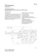
30 Watt Boost Converter
Using The UCC39421 Multimode Synchronous PWM Controller
By Robert B. Diener
1
2
3
4
5
6
7
8
16
15
14
13
12
11
10
9
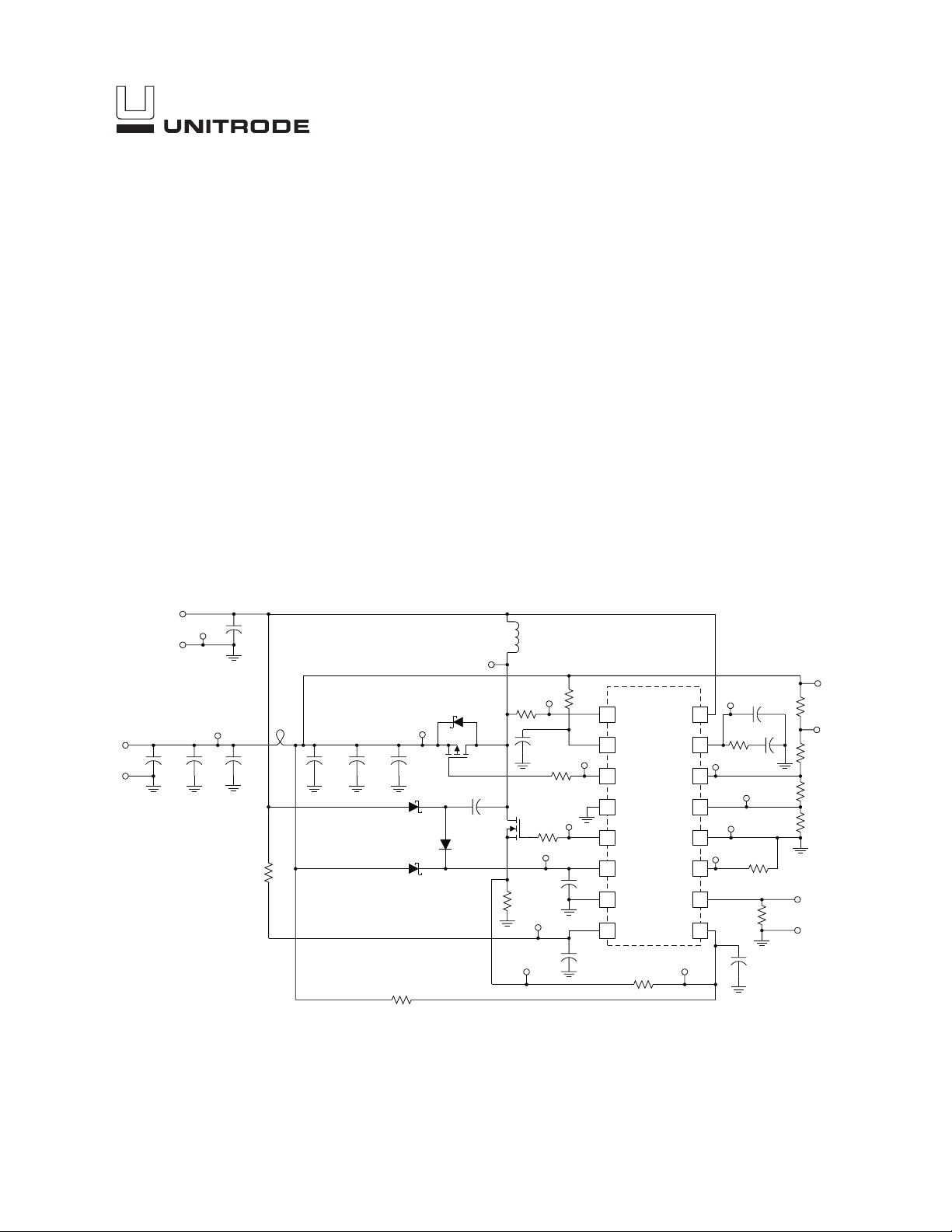
RSEN
VOUT
VGRECT
PGND
CHRG
VPUMP
CP
VIN
RSEL
COMP
FB
PFM
GND
RT
SYNC/SD
ISENSE
UCC39421
R12
100k
C1
330pF
C2
2200pF
R5
1M
R3
0Ω
R2
10k
R1
30k
C5
0.1µF
C4
1µF
R15
0.005Ω
FDS6670A
R6
2K
Q2
C6
0.1µF
R7
1k
L1
3.3µH
V
IN
3.3V
C12
0.1µF
VOUT
5.0V
C11
10µF
R10
200k
SYNC/
SHUTDOWN
R4
470k
Q1
SI4463DY
D1
*OPTIONAL
C3
680µF
P5
P6
TP10
TP7
TP11
TP12
TP13
R11
51Ω
P4
P3
C14
33pF
TP9
TP14
R14
10Ω
TP2
TP3
TP5
R9
0Ω
C13
0.1µF
D4
MMSD914T1
D3
MBR0530LT
D2
MBR0530LT
TP1
C8
680µF
C7
680µF
C9
0.1µF
R8 0Ω
TP8
R13
10Ω
TP4
TP15
TP6
TB1
TB2
+
–
C10
390µF
TP16
TB3
TB4
+
–
L2
BEAD
Figure 1. Schematic diagram.
UDG-99206