
下载
APPLICATION NOTE
VERSATILE UC1834 OPTIMIZES
LINEAR REGULATOR EFFICIENCY
Linear voltage regulators have long been an important resource to power supply
designers. Three terminal, fixed-voltage linear regulators find extensive use as “spot”
regulators and as post-regulation stages fed by switched-mode supplies. However,
while inexpensive and simple to use, these devices have several performance limitations.
First, three terminal regulators are inefficient power converters. Power dissipation in a
linear regulator is given by the relation:
Most monolithic regulators now available require an input-to-output voltage differen-
tial of at least 2 to 3V. This requirement can result in substantial inefficiency, particu-
larly in low voltage supplies. As switched-mode power technology matures, power
losses incurred in linear post-regulation stages are becoming more significant in terms
of overall system efficiency.
Second, fixed-voltage regulators, with fixed maximum output currents, lack versatility.
The use of these devices requires that OEMs maintain large, diverse inventories in order
to support a broad range of power supply requirements.
Third, fixed three-terminal
devices lack the
therefore can exhibit poor
load regulation.
capability of
remote
voltage
sensing,
and
Finally, the most common failure mechanism for linear regulators is a shorted pass
transistor. All critical loads, therefore, require over-voltage protection not provided by
three-terminal regulators.
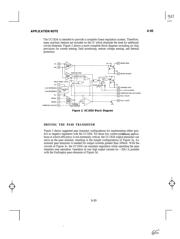
IMPROVED PERFORMANCE WITH UC1834
The UC 1834 is a programmable linear regulator control IC which, with an external pass
transistor, forms a complete linear power supply. This IC provides solutions to all the
above-mentioned drawbacks of three-terminal devices.
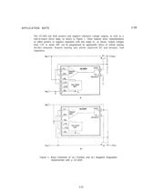
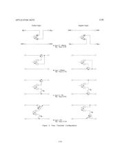
Figure 1 shows the basic elements of positive and negative regulators implemented with
the UC1834. An error amplifier monitors the output voltage and provides appropriate
bias to the pass transistor (Q1) through a driver stage. This high-gain error amplifier
(E/A) allows good dynamic regulation while allowing Q1 to operate near saturation in
the common-emitter mode. The circuits can achieve high efficiency by maintaining
output regulation with an input-to-output voltage differential as low as 0.5V (at 5A).
U-95
3-21