

下载
(max)
V
Maximum Duty Cycle: D =
V η´
OUT
IN
V
IN
V
OUT
I
IN
I
OUT
C
IN
C
OUT
L
D
SW
Application Report
SLVA477B–December 2011–Revised August 2015
Basic Calculation of a Buck Converter's Power Stage
Brigitte Hauke ....................................................................................... Low Power DC/DC Applications
ABSTRACT
This application report gives the formulas to calculate the power stage of a buck converter built with an
integrated circuit having a integrated switch and operating in continuous conduction mode. It is not
intended to give details on the functionality of a buck converter or how to compensate a converter. For
additional information, see the references at the end of this document.
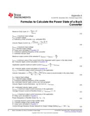
Appendix A contains the formulas without description.
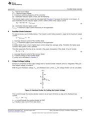
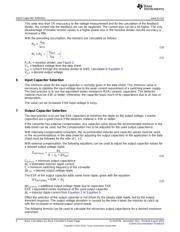
1 Basic Configuration of a Buck Converter
Figure 1 shows the basic configuration of a buck converter where the switch is integrated in the selected
integrated circuit ( IC). Some converters have the diode replaced by a second switch integrated into the
converter (synchronous converters). If this is the case, all equations in this document apply besides the
power dissipation equation of the diode.
Figure 1. Buck Converter Power Stage
1.1 Necessary Parameters of the Power Stage
The following four parameters are needed to calculate the power stage:
1. Input voltage range: V
IN(min)
and V
IN(max)
2. Nominal output voltage: V
OUT
3. Maximum output current: I
OUT(max)
4. Integrated circuit used to build the buck converter. This is necessary because some parameters for the
calculations must be derived from the data sheet.
If these parameters are known, the power stage can be calculated.
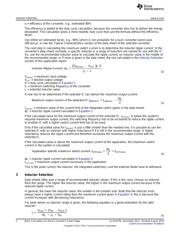
2 Calculate the Maximum Switch Current
The first step to calculate the switch current is to determine the duty cycle, D, for the maximum input
voltage. The maximum input voltage is used because this leads to the maximum switch current.
(1)
V
IN(max)
= maximum input voltage
V
OUT
= output voltage
1
SLVA477B–December 2011–Revised August 2015 Basic Calculation of a Buck Converter's Power Stage
Submit Documentation Feedback
Copyright © 2011–2015, Texas Instruments Incorporated