

下载
21
Analog Applications Journal
Active filters using
current-feedback amplifiers
Introduction
The use of filters in circuit design is very common. They
can be found in circuits such as anti-aliasing for analog-to-
digital converters (ADCs), image rejection for digital-to-
analog converters (DACs), intermediate frequency (IF)
stages in communications systems, and even simple band-
width limiting. However, when the frequency of interest is
higher than a megahertz or two, using a current-feedback
(CFB) amplifier to perform the task of filtering may be a
good choice.
A CFB amplifier has some attributes that make it espe-
cially suited as a very high-frequency filter. These include
the essentially limitless gain-bandwidth product, an inher-
ently low voltage noise at the expense of more current
noise, and the capability for exceptionally high slew rates.
CFB to VFB compensation
One key difference between a voltage-feedback (VFB)
amplifier and a CFB amplifier is that the VFB amplifier
can use a very wide resistance in the feedback path and
maintain a common frequency response characteristic. A
CFB amplifier relies on the feedback-path impedance to
compensate the amplifier and thus does not have nearly
the flexibility in resistance that a VFB amplifier inherently
possesses. With a VFB amplifier, placing a capacitor in the
feedback path will simply cause a pole to form—hence
creating a first-order filter. Doing this to a CFB amplifier,
however, will cause the amplifier to oscillate. Why is this?
Exploration of this subject can be found in several applica-
tion reports (see References 1–3) and will not be repeated
in this article.
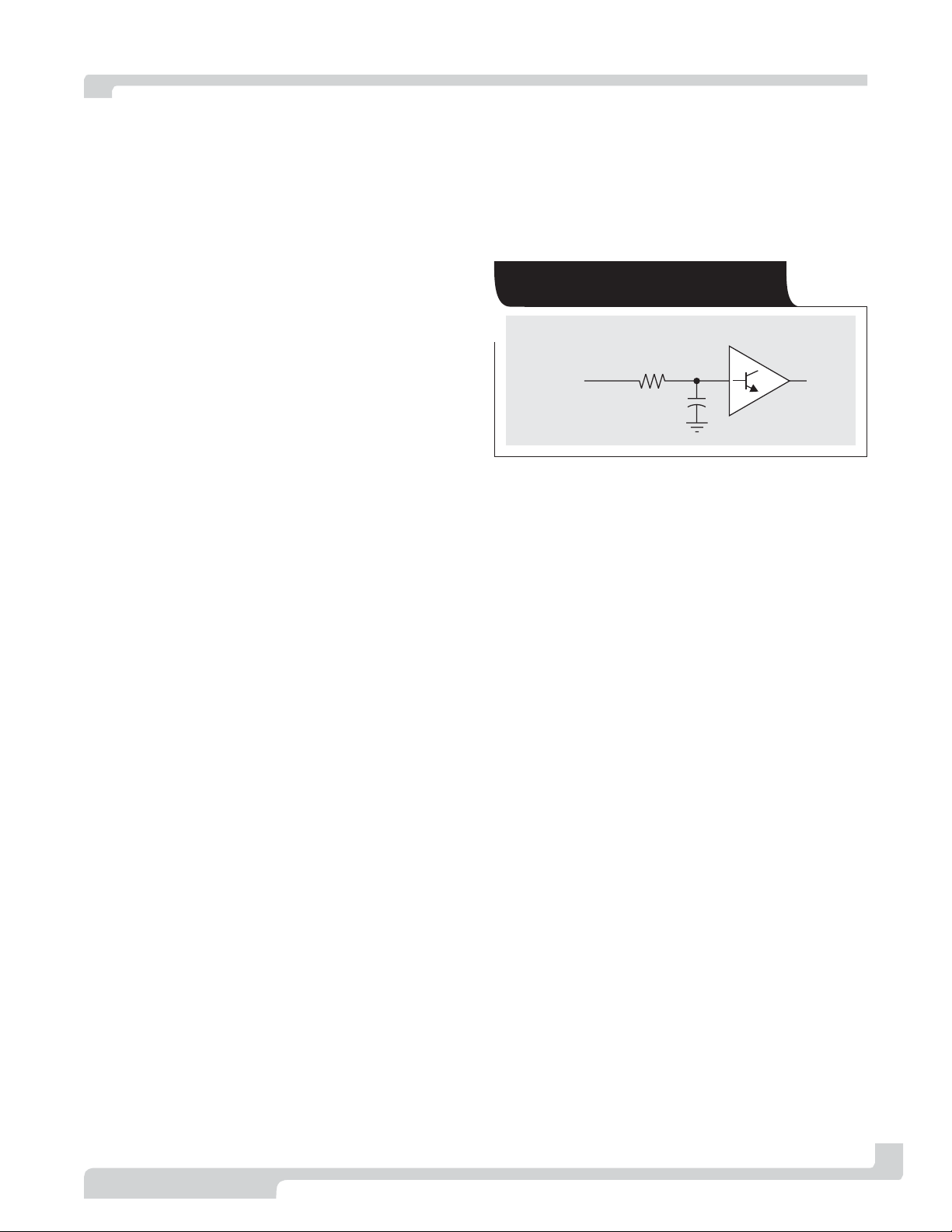
The most simplistic explanation of how a CFB amplifier
is compensated is shown in Figure 1. There is much more
to the CFB amplifier than a simple RC filter and a buffer,
but this is an easy way to see how the amplifier behaves.
The capacitor (C) is internal and fixed, while the resistor
(R) is external and can be visualized as the feedback
resistance. Just like a true RC filter, as R increases, there
is more compensation and the bandwidth decreases; but if
R is decreased too much, the bandwidth will increase to
such a point that the buffer’s own transistor frequency
effects (f
t
) will come into play and cause instability. It is
easy to see that adding a capacitor in parallel with R can-
cels out the C compensation, leading to oscillations.
Reference 4 discusses how to make a CFB amplifier work
even though there may be a capacitor in the feedback loop.
This same technique allows for the construction of any
type of active filter required. To see the advantages of the
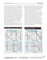
CFB amplifier more clearly, a set of second-order, 0.5-dB-
ripple Chebyshev filters was constructed with a corner
frequency of 40 MHz at gains of ±2 and ±5.
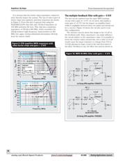
The Sallen-Key filter with gain = +2
The Sallen-Key filter is inherently suitable for CFB ampli-
fiers due to the feedback loop essentially being isolated
from the filter loop. This circuit allows for any resistance
to be used in the feedback loop without directly affecting
the frequency characteristics. A detailed analysis of the
Sallen-Key filter can be examined in Reference 5. Realizing
a design that has proper component values can be quite
time-consuming. To help simplify the process and to mini-
mize the chance of miscalculations, Texas Instruments (TI)
has developed a filter design program called FilterPro
TM
.
FilterPro is available for download at no cost from TI’s
Web site (go to www.ti.com and enter FilterPro in the
Search Keyword field). The program allows for an easy
realization of the desired filter with industry-standard
component values and shows the expected frequency
response of the filter.
One drawback of this tool is that it uses ideal amplifiers.
In the real world, amplifiers have their own bandwidth
limitations that can alter the frequency response of the
filter. As a general rule of thumb, it is desirable to have the
bandwidth of the amplifier at least 10 times higher than
the filter’s corner frequency. Some of the test results
presented later on in this article will show how the ampli-
fier bandwidth can alter the filter’s response.
The 40-MHz, second-order, 0.5-dB Chebyshev filter with
a forward gain of +2 V/V (+6 dB) was constructed with
Texas Instruments Incorporated
Amplifiers: Op Amps
By Randy Stephens (Email: r-stephens@ti.com)
Systems Specialist, Member Group Technical Staff
3Q 2004 www.ti.com/sc/analogapps Analog and Mixed-Signal Products
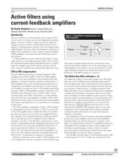
X1 Buffer
R
Feedback
V
OUT
V
Applied
f
t
C
Internal
Figure 1. Simplified compensation of a
CFB amplifier