


下载
23
Analog Applications Journal
Introduction
Although current-feedback (CFB) amplifiers have been
around as long as the widely utilized voltage-feedback (VFB)
amplifiers, their acceptance has been sporadic. One of the
reasons for this is quite simple—they have a different
name and therefore must be difficult and very hard to use.
This is simply not true. There are numerous papers
1, 2, 3
comparing the differences between the two amplifier
types that show they are more similar to each other than
different. In fact, for numerous circuits, a CFB amplifier
may actually yield better results due to its inherent slew-
rate advantage, lack of a gain-bandwidth product, and
reasonably low noise for the performance.
Almost every paper written about CFB amplifiers cautions
readers that placing a capacitor directly in the feedback path,
without any resistance in series, will cause the CFB ampli-
fier to oscillate. This is true, as the compensation of the
amplifier is tied directly to the feedback impedance. Since a
capacitor has low impedance at high frequencies, this essen-
tially places a short in the feedback path that inadvertently
defeats amplifier compensation, resulting in instability.
Because of this limitation, there are a handful of common
circuits that are not recommended for use with a CFB
amplifier. These include integrators, some types of filters,
and special feedback-compensation techniques. But what
if there was a way to make these circuits work? And what
if the solution was as simple as adding a single component?
This would make it feasible to implement a CFB amplifier
for just about every application for which a VFB amplifier
could be used, with the benefits of the CFB amplifier.
Compensation
This article does not explain the compensation theory of
VFB and CFB amplifiers, as there are many papers written
on this topic. The only thing that is important is that
there must be resistance, or impedance, in the feedback
path at the open-loop intersection point to make the CFB
amplifier stable.
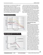
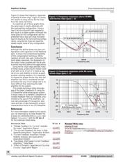
Figure 1 shows a traditional VFB amplifier, a THS4012,
configured in a noninverting gain of +5 with a simple low-
pass gain filter set at approximately 1 MHz by the straight-
forward 1/(2πR
F
C
F
) formula.
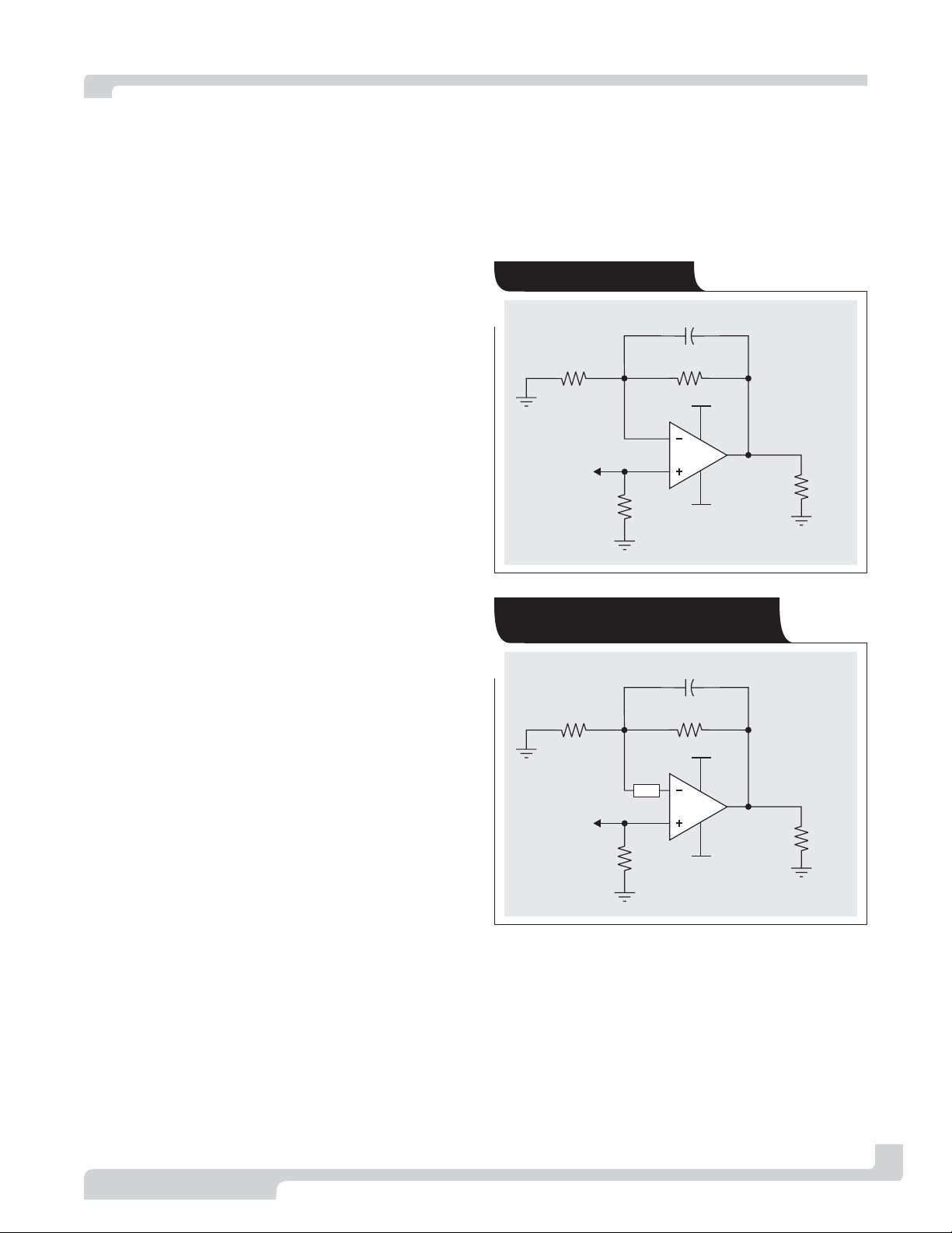
If a CFB amplifier like the THS3112 is simply dropped
into this circuit, it will oscillate and the circuit will
become useless. A method of compensating the CFB
amplifier in this circuit is to insert a resistance, or imped-
ance (Z), in the feedback path as shown in Figure 2.
It can easily be seen that regardless of the impedance
of the feedback path represented by R
F
and C
F
, the
impedance Z is in the amplifier’s feedback loop dictating
the compensation of the amplifier. The interesting thing
about this configuration is that the feedback resistance
(R
F
), which normally dictates the compensation of the
amplifier, can now be essentially any resistance desired.
The reader should keep in mind that this is still a high-
speed amplifier with speeds over 100 MHz; so the feedback
resistance should always be kept less than a few kilohms
to minimize the effects of parasitic capacitances on the
overall circuit. Conversely, minimizing the resistance too
much will place too much of a load on the amplifier,
typically degrading performance.
One of the drawbacks of adding the impedance Z in this
manner is that the summing node at the inverting terminal
is now separated from the virtual summing node. This can
Texas Instruments Incorporated
Amplifiers: Op Amps
By Randy Stephens (Email: r-stephens@ti.com)
Systems Specialist, Member Group Technical Staff
3Q 2003 www.ti.com/sc/analogapps Analog and Mixed-Signal Products
C = 220 pF
F
THS4012
R = 750
F
Ω
R
100
L
Ω
R
50
Term
Ω
–15 V
+15 V
V
IN
V
OUT
R = 187
G
Ω
Figure 1. VFB test circuit
C = 220 pF
F
THS3112
R = 750
F
Ω
R
100
L
Ω
R
50
Term
Ω
–15 V
+15 V
Z
V
IN
V
OUT
R = 187
G
Ω
Figure 2. CFB test circuit with simple
modification
Expanding the usability of
current-feedback amplifiers