


下载
®
1/11
AN2025
APPLICATION NOTE
Converter Improvement Using
Schottky Rectifier Avalanche Specification
REV. 1AN2025/1004
STMicroelectronics gives in product datasheets useful information for all their Schottky Rectifier families
to define their working limit in the avalanche area. A simple method to determine if a Schottky diode can
work in the avalanche area in a given Switch Mode Power Supply (SMPS) is described in this document.
Then an accurate method will be defined in order to estimate the maximum average avalanche power
losses. Finally, a concrete example will be illustrated to show how the choice of a Schottky diode can be
optimized in order to improve the efficiency of the converter.
I. Introduction
The design of SMPS is subjected to heavy constraints in order to improve the trade-off between the cost
and the power density. One way to respond to these aggressive specifications is to drive components
closer to their intrinsic limits. The use of Schottky diodes in the avalanche area is a good example of this
evolution.
II. Description of the specification tool
STMicroelectronics guarantees for each Schottky diode a reference avalanche power capability corre-
sponding to a rectangular current pulse: P
ARM
(1µs, 25°C) (given at t
p
=1µs and T
j
= 25°C) - See figure 1.
Derating curves shown in figure 2 and figure 3 give
the admissible avalanche power for each Schottky
diode versus the operating junction temperature
(T
j
) and the pulse duration (t
p
).
P
ARM
(1µs,25°C) for each part number as well as
derating curves are given in the respective data
sheet.
The designer must ensure that the guaranteed av-
alanche power P
ARM
(t
p
,T
j
) is greater than the av-
alanche power in the application P
AVALANCHE
:
P
AVALANCHE
(application) < P
ARM
(t
p
, T
j
)
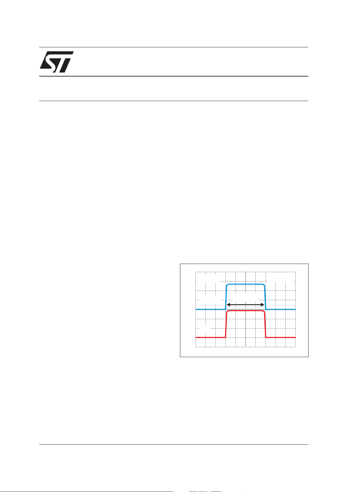
Figure 1: P
ARM
(1µs, 25°C) (Maximum repetitive
avalanche power)
V
Clamp
T = 25°C
j
I
PP
SCOPE
t = 1µs
p
P (1µs, 25°C) = V
ARM Clamp PP
x I