

下载
INTRODUCTION
Although Surface Acoustic Wave Coupled-Resonator
(SAW CR) filters have been readily available for several
years, two issues currently inhibit the effective use of this
technology: 1) Rapidly evolving technical performance has
resulted in a lack of awareness by the design community of
current capabilities, and 2) Systems originally designed for
conventional filtering technologies, often cannot achieve
optimum performance and cost because SAW CR filters
were not considered in the initial system design.
Single-pole resonators using SAW cavities were first pro-
posed in 1970. [1, 2] By the mid 1970’s, single-pole resona-
tors were becoming practical and multi-pole SAW CR filters
were shown to be feasible. [3, 4] In the early 1980’s, CR
filters of up to six poles were demonstrated [5-7] and two-
pole SAW CR filters became readily available in quantity
and at reasonable cost. SAW CR filters at frequencies as high
as 1500 MHz were demonstrated in the mid 1980’s. [8]
In spite of the knowledge of SAW CR filter capabilities in
the ultrasonics community and the availability of practical
devices in production volumes, this particular technology is
still not well known among RF circuit and system designers.
A surprisingly large percentage of RF design engineers seem
unaware of the capabilities presently available and the de-
sign possibilities made viable by this technology.
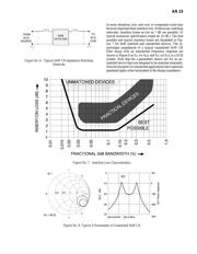
SAW CR filters possess narrow bandwidths (typically 0.03%
to 0.6%), low insertion losses (as low as 2 dB), and good
ultimate rejection without harmonic spurious responses.
Combined with center frequencies up to 1650 MHz, this type
of filter is ideal for many consumer, industrial, and military
applications in signal selection and frequency control. In
addition, SAW CR filters often offer the smallest size and
lowest unit cost of any of the alternatives.
In this application note, a brief overview of basic SAW CR
filter concepts is followed by a description of current practi-
cal performance capabilities important to the RF design
engineer. The capabilities of SAW CR filters are then com-
pared with other passive bandpass filter technologies with an
emphasis on optimizing the selection process at the system
design level. As a design aid, a reference chart is presented
covering practical, passive devices in the frequency range of
10 MHz to 10 GHz. Several application examples of SAW
CR filters are also presented.
THE BASIC CONCEPT
Theory of operation is not the subject of this application
note. However, a very brief review and description of the
basic concepts is in order as a point of reference for the RF
design engineer.
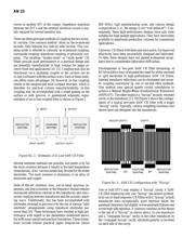
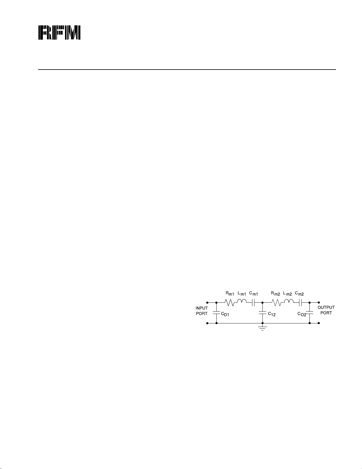
In and near the passband, the SAW CR filter may be modeled
by the two-pole lumped element equivalent circuit shown in
Figure 1. In this model, R
m
, L
m
, and C
m
are the motional
resistance, inductance, and capacitance values of each acous-
tic resonant cavity. C
o
is static capacitance which includes
both case parasitic capacitance and capacitance between
electrodes. C
12
represents the acoustic coupling between the
two resonant cavities, and as a practical matter, also includes
parasitics. (This model is not valid in the reject band, how-
ever.) [9]
The SAW CR filter relies on the piezoelectric effect. Electric
waves are converted into surface acoustic waves at the input
of the device by an Inter-Digital Transducer (IDT) com-
posed of metal electrodes on, or recessed into, the surface of
a substrate material. These acoustic waves excite a half
wavelength (λ/2) resonant acoustic cavity formed between
the transducer and a reflective grating, or within the
transducer itself. Energy is then coupled to another λ/2
resonant acoustic cavity and converted back to electric
by Allan Coon
December, 1990
Capabilities and Applications of
SAW Coupled-Resonator Filters
AN 23
Figure No. 1: 2-Pole LC Equivalent Model