
下载

For technical support and more information, see inside back cover or visit www.ti.com/powertrends
All Products
All Texas Instruments surface mount Plug-in Power
Products are designed to be compatible with industry
standard low temperature solder reflow processes and
aqueous washes. This application note identifies requirements
for soldering Plug-in Power modules to a host PCB.
Soldering Requirements
1 - Low Temperature Solder Process:
Plug-in Power modules must be attached to the host PCB
using industry standard low-temperature solder reflow pro-
cesses. The solder paste should be 63% tin, 37% lead or
similar solder, with a nominal melting point of 183°C.
2 - Quantity of Solder:
Power components usually require more solder paste than
other SMT devices to ensure an electrically and mechani-
cally reliable solder joint. Power component leads can
have 5 or more amperes of current flowing through a
single solder joint, and use larger leads for attachment to
a host PCB. For these reasons, a solder paste thickness of
0.008 to 0.010 inches is recommended for the Plug-in
Power modules as opposed to 0.006 inches for typical
SMT components. A solder stencil with varying height,
(step screen) is one method of applying thicker paste to
only the power component solder pads.
3 - Reflow Profile:
TO AVOID COMPONENT DAMAGE AND POTEN-
TIAL OPENS OR SHORTS DUE TO EXCESSIVE
TEMPERATURE OR INTERNAL SOLDER REFLOW
WITHIN THE PRODUCT, USE THE FOLLOWING
MAXIMUM REFLOW PARAMETERS:
A. PREHEAT AND COOL DOWN RAMPS SHOULD
NOT EXCEED 2°C/SECOND TO PREVENT
INTERNAL COMPONENT FAILURES DUE TO
THERMAL STRESS.
B. DO NOT ELEVATE THE PRODUCT'S CASE, PIN,
OR INTERNAL COMPONENT TEMPERATURES
ABOVE A PEAK OF 215°C.
C. DO NOT EXCEED 183°C PIN OR CASE
TEMPERATURE FOR A TIME PERIOD GREATER
THAN 120 SECONDS.
Developing Your Own Reflow Profile
A reliable profile for soldering power modules to a host PCB
may be developed using at least three small gauge (30 to 36 Awg)
thermocouples secured to the test unit in the following locations:
• Product signal pin near the module’s PCB
• Center of the case
• Product ground pin near customers PCB
Monitor thermocouples as the unit passes through the oven
to verify that the pin temperature exceeds 183°C for at least 40 to
60 seconds, and that the soldering requirements detailed
herein are not exceeded.
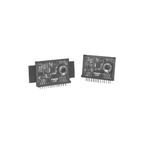
Power Module Construction
Plug-in Power Products are constructed on FR-4 or ceramic
printed circuit boards using surface mount components. The
components are soldered in place using 96.5% tin, 3.5% silver,
high temperature solder. This solder has a melting temperature
of 221 ±4°C.
Connecting pins and solderable case connections use 100%
tin plating and are lead free. Typical plating for both is 200 to
300 microinches of 100% tin over 50 to 100 microinches
of Nickel. All soldering surfaces meet and are routinely tested to
the solderability requirements of ANSI/J-STD-002, Category 3.
Surface Mount Soldering Qualification
All Texas Instruments Plug-in Power Products are quali-
fied to have no degradation from reflow/IR soldering and
aqueous washing by verification through rigorous testing.
Sample batches are subjected to three passes through a
convection reflow oven and an aqueous wash cleaner, with a
cool down between passes to room temperature. The con-
vection reflow oven is set to achieve a 215°C peak temperature
on the components. These parts are subsequently used for
thermal shock, humidity and life qualification testing. All
products must pass this initial qualification testing with zero
failures before being released to production.
Additional Considerations
Each host PCB and Plug-in Power module assembly
may be physically different. Each assembly should be
individually verified to be within these soldering require-
ments.
The Plug-in Power modules are designed to be ther-
mally efficient in transfering heat from their internal
components through convection, conduction, and radia-
tion. During soldering, heat therefore flows easily into the
power module. As a result, the module’s internal components
and solder joints may heat at different rates than the host
PCB and it's SMT components.
Application Notes—AN22
SLTA051 SEPTEMBER 2000
Reflow Soldering Requirements for Plug-in Power
Surface Mount Products