
下载
2004 Microchip Technology Inc. DS00937A-page 1
AN937
INTRODUCTION
Continuous processes have been controlled by
feedback loops since the late 1700’s. In 1788, James
Watt used a flyball governor on his steam engine to
regulate its speed. The Taylor Instrument Company
implemented the first fully functional Proportional,
Integral and Derivative (PID) controller in 1940.
Although feedback control has come a long way since
James Watt, the basic approach and system elements
have not changed. There are several elements within a
feedback system; for discussion purposes, we will use
a home heating temperature control system as our
model in the descriptions below.
• Plant – The physical heating and cooling parts of
the system.
• Sensors – The devices (thermistors measuring
temperature) that measure the variables within
the Plant.
• Setpoint – This is a value (i.e., 70 degrees),
which is converted to a voltage that the process
drives towards.
• Error Signal – This is the difference between the
response of the Plant and the desired response
(Setpoint). In a house, the thermostat may be set
to 70 degrees, but the temperature is actually
65 degrees, therefore resulting in an error of
5 degrees (Error = Setpoint – Measured).
• Disturbances – These are unwanted inputs to
the Plant, which can be common. A disturbance
would be an open entry door allowing a gust
of cold air to blow in, quickly dropping the
temperature and causing the heat to come on.
• Controller – Intentionally left for last, this is the
most significant element of a control system. The
Controller is responsible for several tasks and is
the link that connects together all of the physical
and nonphysical elements. It measures the output
signal of the Plant’s Sensors, processes the
signal and then derives an error based on the
signal measurement and the Setpoint. Once the
sensor data has been collected and processed,
the result must be used to find PID values, which
then must be sent out to the Plant for error
correction. The rate at which all of this happens is
dependent upon the Controller’s processing
power. This may or may not be an issue
depending on the response characteristic of the
Plant. A temperature control system is much more
forgiving on a Controller’s processing capabilities
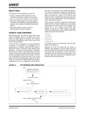
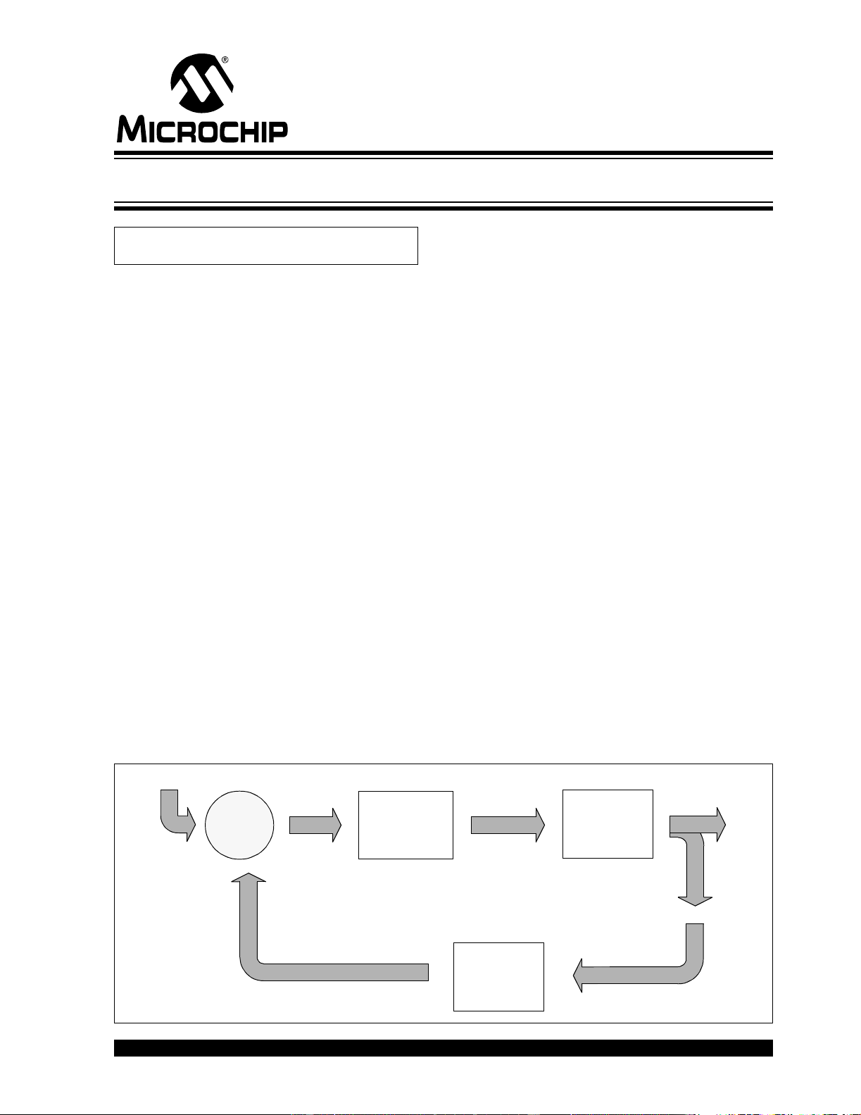
than a motor control system. Figure 1 shows a
basic block diagram of a feedback control system.
FIGURE 1: FEEDBACK CONTROL LOOP
Author: Chris Valenti
Microchip Technology Inc.
Controller
Plant
Feedback
Setpoint
Error
Controller
Output
Process
Variable
–
+
Implementing a PID Controller Using a PIC18 MCU