


下载

2004 Microchip Technology Inc. DS00899A-page 1
AN899
INTRODUCTION
The PIC18F2331/2431/4331/4431 family of micro-
controllers have peripherals that are suitable for motor
control applications. These peripherals and some of
their primary features are:
• Power Control PWM (PCPWM)
- Up to 8 output channels
- Up to 14-bit PWM resolution
- Center-aligned or edge-aligned operation
- Hardware shutdown by Fault pins, etc.
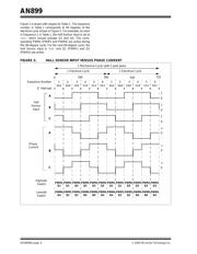
• Quadrature Encoder Interface (QEI)
- QEA, QEB and Index interface
- High and low resolution position
measurement
- Velocity Measurement mode using Timer5
- Interrupt on detection of direction change
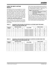
• Input Capture (IC)
- Pulse width measurement
- Different modes to capture timer on edge
- Capture on every input pin edge
- Interrupt on every capture event
• High-Speed Analog-to-Digital Converter (ADC)
- Two sample and hold circuits
- Single/Multichannel selection
- Simultaneous and Sequential Conversion
mode
- 4-word FIFO with flexible interrupts
In this application note, we will see how to use these
features to control a Brushless DC (BLDC) motor in open
loop and in closed loop. Refer to the Microchip applica-
tion note, “AN885, Brushless DC (BLDC) Motor
Fundamentals” (DS00885), for working principles of
Brushless DC motors and basics of control. Also, to
obtain more information on motor control peripherals and
their functions, refer to the PIC18F2331/2431/4331/4431
Data Sheet (DS39616).
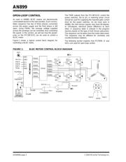
HARDWARE
A PICDEM™ MC demo board was used to develop,
test and debug the motor control code. The PICDEM
MC has a single-phase diode bridge rectifier, convert-
ing AC input to DC and a power capacitor bank that
keeps a stable DC bus. A 3-phase IGBT-based inverter
bridge is used to control the output voltage from the DC
bus. Figure 1 shows the overall block diagram of the
hardware.
The control circuit and power circuits are optically iso-
lated with respect to each other. An on-board fly-back
power supply generates +5VD, with respect to the
digital ground used for powering up the control circuit,
including the PICmicro
®
device. +5VA and +15VA are
generated with respect to the power ground (negative
of DC bus). The feedback interface circuit is powered
by +5VA, while +15VA supplies power to the IGBT
drivers located inside the Integrated Power Module
(IPM).
With the optical isolation between power and control
circuits, programming and debugging tools can be
plugged into the development board when main power
is connected to the board. The board communicates
with a host PC over a serial port configured with an on-
chip Enhanced USART. The on-board user interface
has two toggle switches, a potentiometer and four
LEDs for indication.
In this application note, the switch SW1 is used to
toggle between motor Run and Stop and SW2 is used
to toggle between the direction of motor rotation. Each
press of these buttons will change the state. A potenti-
ometer is used for setting the speed reference. The
LEDs are used for indication of different states of
control.
Reference copies of the PICDEM™ MC schematics can
be found in Appendix B: “Circuit Schematics”.
Author: Padmaraja Yedamale
Microchip Technology Inc.
Brushless DC Motor Control Using PIC18FXX31 MCUs