
下载
®
©
1999 Burr-Brown Corporation AB-148 Printed in U.S.A. May, 1999
The information provided herein is believed to be reliable; however, BURR-BROWN assumes no responsibility for inaccuracies or omissions. BURR-BROWN
assumes no responsibility for the use of this information, and all use of such information shall be entirely at the user’s own risk. Prices and specifications are subject
to change without notice. No patent rights or licenses to any of the circuits described herein are implied or granted to any third party. BURR-BROWN does not
authorize or warrant any BURR-BROWN product for use in life support devices and/or systems.
LOW SAMPLING RATE OPERATION FOR BURR-BROWN
AUDIO DATA CONVERTERS AND CODECS
By Robert Martin and Hajime Kawai
PURPOSE
This application bulletin describes the operation and perfor-
mance of Burr-Brown’s PCM digital audio products when
using low sampling frequencies.
INTRODUCTION
For most consumer audio applications, customers using
Burr-Brown’s PCM digital audio products will operate at a
standard audio sampling frequency, such as 44.1kHz, 48kHz,
or 96kHz. However, there are applications where lower
sample rates are either desirable or required. These applica-
tions include computer audio, telephones, intercom systems,
speech processing, video teleconferencing, and modems.
For these applications, sample rates from 8kHz to 22.05kHz
are very common.
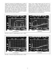
Although Burr-Brown concentrates its PCM design efforts
to obtain specified performance using sampling frequencies
in the 32kHz to 96kHz range, most PCM products can
support sampling rates as low as 4kHz while achieving near
typical dynamic performance. The following sections will
examine the low sampling frequency operation and perfor-
mance of Burr-Brown’s PCM products, with emphasis on
understanding the operational and performance limitations,
as well as circuit design considerations for these applica-
tions.
GENERAL CONSIDERATIONS FOR DELTA-SIGMA
DATA CONVERTERS
For delta-sigma data converters, theoretical dynamic perfor-
mance is given by the performance of the digital filter,
modulator, and output amplifier sections. Delta-sigma data
converters use high oversampling rates, such as 64f
S
, or 64
times the desired sample rate. This oversampling in the
digital filter and modulator section automatically tracks with
changes in sample frequency, f
S
. Overall performance of the
digital filter and modulator remains relatively constant over
the range of usable sampling frequencies.
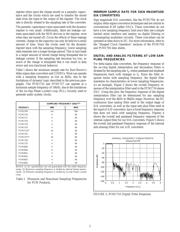
Circuitry external to the data converter also impacts the
overall dynamic performance. These circuits include low
TM
pass filters used for digital-to-analog (D/A) post filtering
and analog-to-digital (A/D) anti-aliasing filtering. These
filters are required in order to limit the output and input
signal bandwidth.
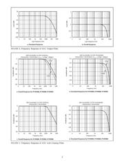
DYNAMIC LOGIC AND ITS EFFECT ON MINIMUM
SAMPLE RATE FOR DELTA-SIGMA CONVERTERS
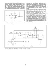
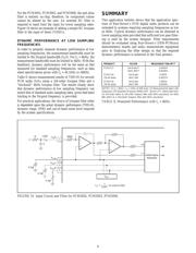
Delta-sigma data converters utilize dynamic logic circuits,
especially in their oversampling digital filter sections. Fig-
ures 1 and 2 show the equivalent circuit and transistor level
circuit diagram of a dynamic logic register. The dynamic
FIGURE 1. Simple Equivalent Circuit for Dynamic Reg-
ister.
V
I
φ
1
φ
2
V
O
Parastic
Capacitor
Basic Concept of Dynamic Register
Parastic
Capacitor
CLK1
V
I
V
O
CLK2
p-ch
p-ch
n-ch
p-ch
n-ch
n-ch
FIGURE 2. Transistor Level Circuit Diagram of Dynamic
Register.
SBAA033