
下载
© Semiconductor Components Industries, LLC, 2010
December, 2010 - Rev. 7
Publication Order Number:
AND8443/D
1
www.onsemi.com
APPLICATION NOTE
AND8443/D
Timing-Safe
™
Spread
Spectrum EMI Reduction
Conventional Spread Spectrum
Spread spectrum electromagnetic interference (EMI) reduction is a technique in which the frequency of a clock signal is increased or
decreased gradually, and then brought back to its original frequency. By “spreading” electromagnetic energy over a narrow band of
the frequency spectrum, the energy spikes of the frequencies and harmonics are smoothed over, hence reducing EMI. The technique is
effective when applied to systems where a single master clock acts as the source of the system timing and all other clock and data signals
derive their timing from this source. However, it can invite data synchronization problems when attempts are made to use this technique
directly on selected independent sub-system clocks.
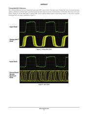
What is Timing-Safe™?
Timing-Safe technology solves a major drawback of traditional spread spectrum EMI reduction—the potential misalignment of clock and
data paths. Timing-Safe achieves this by limiting variations in signal frequencies to dened regions corresponding to clock edges. The
technique effectively reduces the peak amplitudes of clock signals—thereby ensuring compliance with FCC standards—while maintaining
synchronization throughout the system and protecting data integrity.
Faster data rates have made EMI FCC compliance a difcult challenge. The designer’s rst choice is to spread the master clock at its
origin. This approach keeps the data and the clock synchronized throughout the system. Often the master clock gets distributed to multiple
sub-systems. Several sub-systems could function well with the master clock having spread spectrum. In certain designs; however, sub-
system clocks may require independent EMI spreading. In such a case, the data and the clock can lose synchronization, manifesting itself
as cycle slip. A Timing-Safe buffer provides spread spectrum clock modulation for EMI reduction without the associated cycle slip. These
devices can be inserted directly into the sub-system clock path as an Active Bead™ EMI lter. This allows a true drop-in solution to reduce
sub-system EMI.
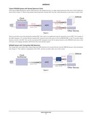
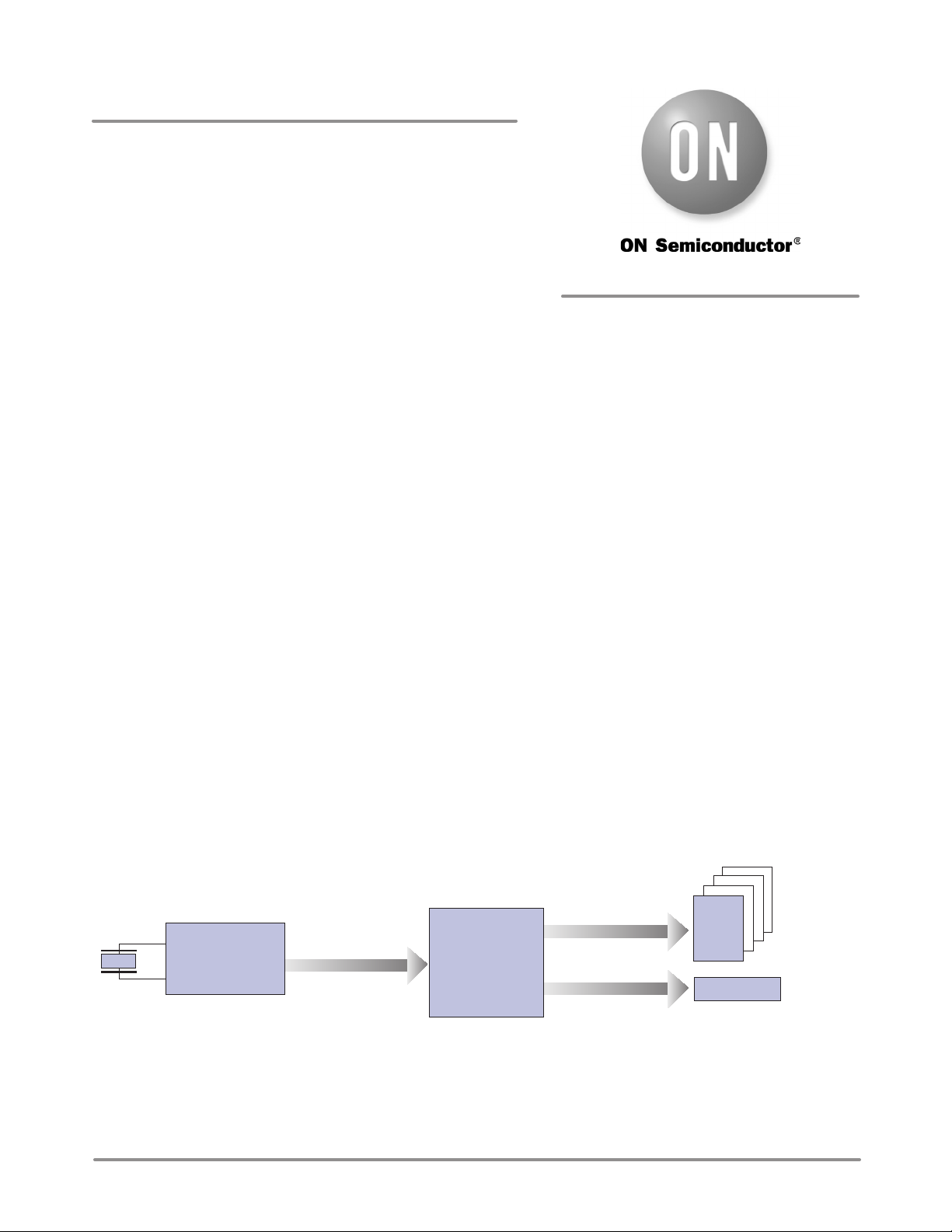
Typical SDRAM System without Spread Spectrum Clock
A typical SDRAM platform is illustrated in the example below (Figure 1). In this conguration, EMI is often found to be radiating from
the SDRAM clocks.
Figure 1.
Clock
Synthesizer
SDRAM
Other Devices
Master Clock
Memory Clocks
Other Clocks
ASIC