


下载
Application Bulletin Number 85
APPLICATION BULLETIN
®
Mailing Address: PO Box 11400 • Tucson, AZ 85734 • Street Address: 6730 S. Tucson Blvd. • Tucson, AZ 85706
Tel: (602) 746-1111 • Twx: 910-952-111 • Telex: 066-6491 • FAX (602) 889-1510 • Immediate Product Info: (800) 548-6132
SIMPLE CIRCUIT DELIVERS
38Vp-p AT 5A FROM 28V UNIPOLAR SUPPLY
by Jason Albanus (602) 746-7985
Since the first analog IC requiring bipolar supplies was
developed, people have been trying to operate them from
unipolar supplies. Not only do the “headroom” (V
S
– V
OUTMAX
)
requirements come into play, but with a unipolar supply
typically come unipolar outputs. To get bipolar output swings
from a unipolar supply, drive the load differentially and
create a reference signal which can be used a “pseudo
ground” for amplifier and input signal reference. This cir-
cuit topography requires that your signal be elevated to
V
S
÷ 2.
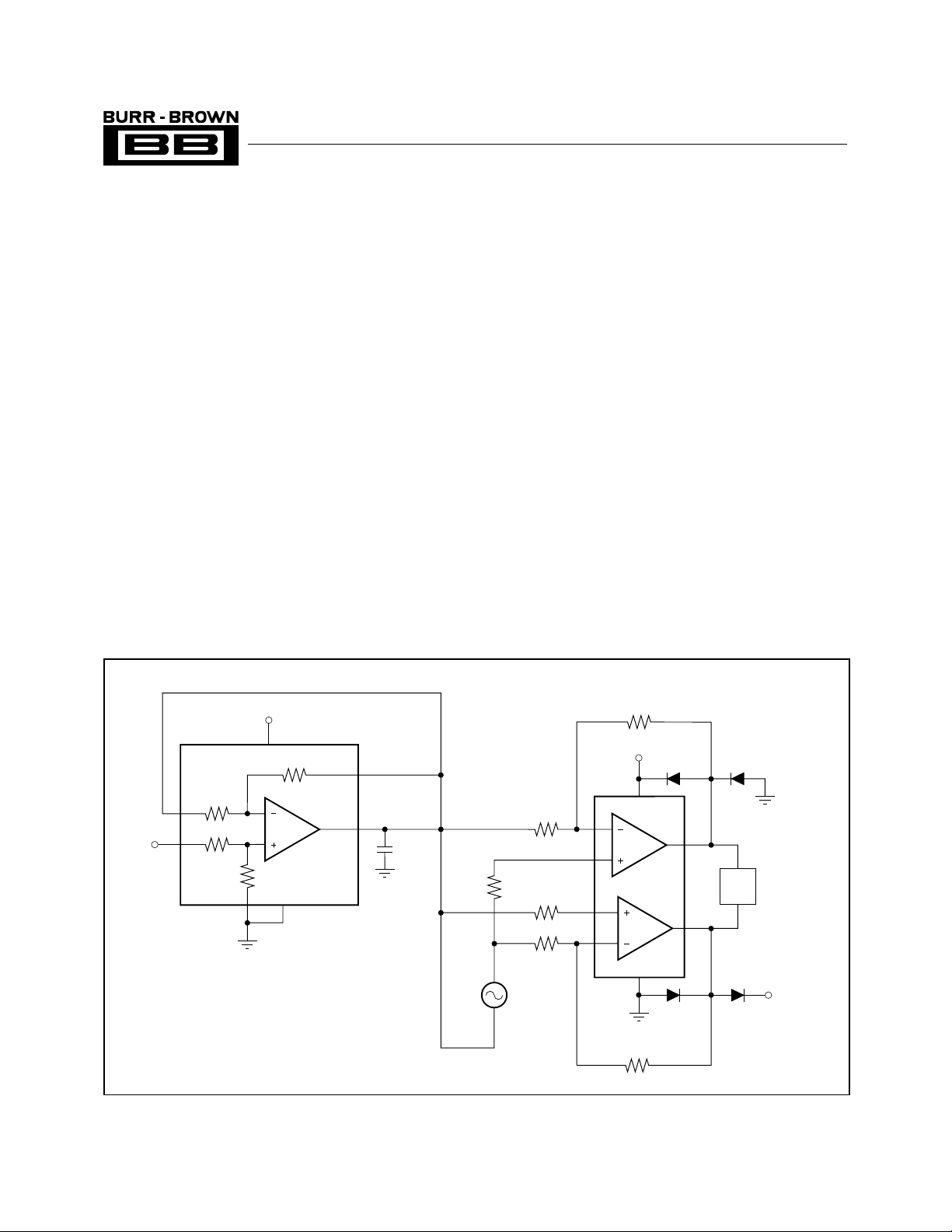
The INA105 is a precision unity gain differential amplifier,
and as a low cost monolithic circuit, it offers high reliability
and accuracy. With an initial offset voltage of 50µV, gain
error of 0.005%, and small signal bandwidth of 1MHz, the
INA105 makes an ideal amplifier for creating this pseudo
ground. The OPA2541 is a dual power operational amplifier
capable of operation from power supplies up to ±40V (or a
single, unipolar 80V) at output currents of 5A continuous.
With two monolithic power amplifiers in a single package it
provides unequaled functional density, and provides the
means to deliver differential outputs at high power. By using
the INA105 to create the pseudo ground, and the OPA2541
to drive 5A loads differentially, the circuit in Figure 1 can be
developed. At 5A output current, the OPA2541 requires a
typical headroom of 4.5V, and as configured, output voltage
swings of 2V
S
– 18V (peak-to-peak) can be achieved. The
output swing can be calculated by realizing that when one of
the amplifiers reaches its positive output limit (V
S
–
V
HEADROOM
), the other amplifier should reach its negative
output limit (0V + V
HEADROOM
). This creates a voltage swing
FIGURE 1. Single Supply, Bipolar Output Swing for Floating Signal Source.
V
S
5
6
3
INA105
25kΩ
25k
Ω
1000pF
V
S
7
1
2
25kΩ
25kΩ
4
1
OPA2541
V
S
2
R
6
7.5kΩ
5
R
2
10kΩ
B
R
1
15kΩ
4
A
3
7
8
R
5
10.2kΩ
R
3
6.04kΩ
R
4
25.5kΩ
Load
V
A
V
B
D
1
D
2
D
3
D
4
V
S
V
LOAD
= V
A
– V
B
6
V
IN
D
1
– D
4
= Protection Diodes
for EMF Generating Loads
©
1994 Burr-Brown Corporation AB-085 Printed in U.S.A. February, 1994
SBOA037