

下载
1
1
3
4
©
1997 Burr-Brown Corporation AB-121 Printed in U.S.A. December, 1997
®
PRECISION ABSOLUTE VALUE CIRCUITS
By David Jones (520) 746-7696, and Mark Stitt
You can build a precision absolute value circuit using two op
amps and two precision resistors. If you use an op amp and
an IC difference amplifier, no user supplied precision resis-
tors or resistor adjustments are required. Circuits shown are
suitable for precision split supply operation and for single-
supply operation. When used with a rail-to-rail op amp, the
single supply circuit can approach a 0 to 5V full-wave
rectified output from a ±5V input when operating from a
single +5V power supply.
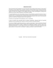
The circuit shown in Figure 1 is a split supply circuit
preferred when high input impedance is desired. To under-
stand how the circuit works, notice that for positive input
signals D
1
becomes reverse biased resulting in the active
circuit fragment shown in Figure 2. A
1
drives the non-
inverting input of A
2
through forward biased diode D
2
. The
feedback to the inverting inputs of A
1
and A
2
is from the
output of A
2
through resistors R
1
and R
2
. Since no current
flows through resistors R
1
or R
2
, in this condition, V
OUT
is
precisely equal to V
IN
.
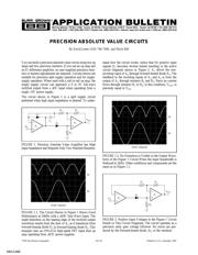
FIGURE 2. Positive Input Voltages to the Figure 1 Circuit
Result in This Circuit Fragment. The circuit operates as a
precision unity gain voltage follower. No errors are pro-
duced by the forward-biased diode, D
2
, or the resistors.
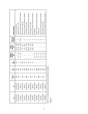
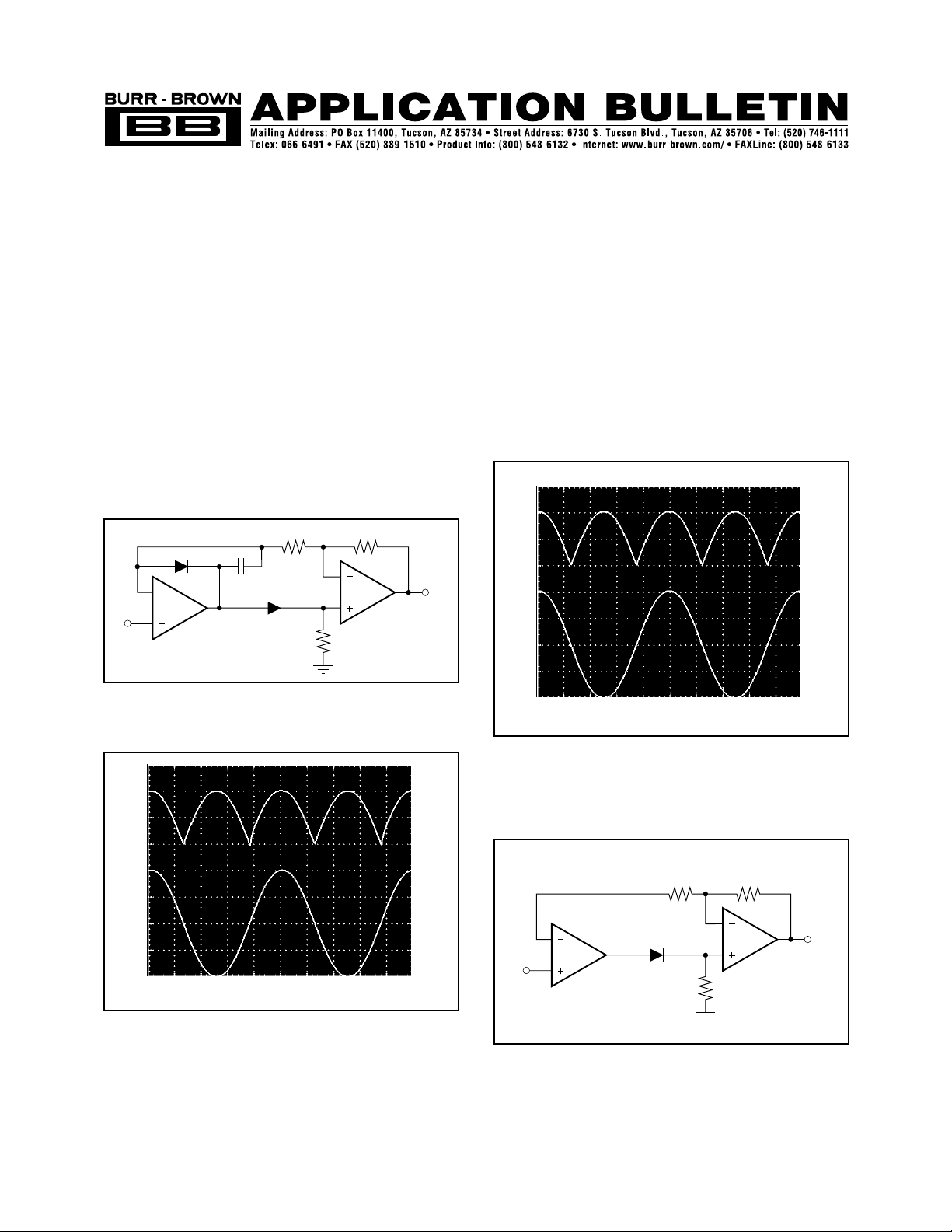
FIGURE 1.2. No Distortion is Visible in the Output Wave-
form of the Figure 1 Circuit When the Input Bandwidth is
Reduced to 2kHz. Other conditions and components are the
same as in Figure 1.1.
A
2
R
2
R
3
R
1
D
2
V
OUT
V
IN
A
1
A
2
R
2
R
3
R
1
D
2
C
1
D
1
V
OUT
V
IN
A
1
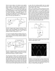
FIGURE 1. Precision Absolute Value Amplifier has High
Input Impedance and Requires Only Two Matched Resistors.
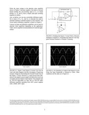
FIGURE 1.1. The Circuit Shown in Figure 1 Shows Good
Performance at 20kHz with a ±10V Sine Wave Input. The
slight distortion on the leading edge of the rectified output
waveform results from the slew of A
1
as it transitions from
forward biasing diode D
1
to forward biasing diode D
2
. This
example uses an OPA2132 high-speed FET input dual op
amp operating from ±15V power supplies.
0V
0V
5V/div 10µs/div
0V
0V
5V/div 100µs/div
SBOA068