


下载
© Semiconductor Components Industries, LLC, 2012
December, 2016 − Rev. 3
1 Publication Order Number:
AND9031/D
AND9031/D
Constant Current Regulator
Charging Circuit
Abstract
This application note describes how a Constant Current
Regulator, CCR, can be used in a low cost charging circuit
for rechargeable batteries, providing a simple controller to
terminate charging.
Figure 1. Block Diagram of Charging Circuit
+
−
Source
Current
Control
Voltage
Reference
Charge
Indicator
Controller
Battery
Types of Rechargeable Batteries
The three most common rechargeable batteries are Nickel
Metal Hydride (NiMH), Nickel Cadmium (NiCad), and
Lithium Ion (Li-Ion). When referring to the rate at which
a battery is charged the letter “C” is used. The “C” defines
the capacity of the battery over 1.0 hour. For example,
a battery rated at 800 mAh could be charged at 0.5C
resulting in a charge current of 400 mA over two hours to
fully charge the battery.
Nickel Metal Hydride and Nickel Cadmium
The nominal voltage of a NiMH battery is 1.2 V/cell and
should be charged up to 1.5−1.6 V/cell. There are several
different techniques for determining when to shutoff the
charge. They include: peak voltage detection, negative delta
voltage, delta temperature (dT/dt), temperature threshold,
and timers. For high end chargers these may be all combined
into one charger.
The CCR charger is a peak voltage detect circuit and
terminates charging at a predetermined peak. The
predetermined peak voltage is 1.5 V/cell, and will charge the
battery to ≈ 97%.
Nickel Cadmium batteries can be charged using this
circuit. They perform very similar to NiMH batteries so this
method will work well for them.
Lithium Ion
The usual method of charging a Li-Ion battery is to charge
the battery to 4.2 V/cell at 0.5C to 1C followed by a trickle
charge. The temperature rise of Li−Ion batteries should be
kept below 5°C while charging, a higher temperature rise
indicates a potential to combust. The trickle charge portion
of the charge cycle is when the battery temperature rises the
most and it has the greatest chance to combust. High end
charges use smart IC’s, such as the NCP1835B, to monitor
and control the charge of Lithium ion batteries because of
this issue.
The CCR controller discussed here eliminates this by not
including a trickle charge, keeping the battery in a safe
operating area and helping to increase the life of the battery.
However, by eliminating the trickle charge the battery will
only receive ≈ 85% charge.
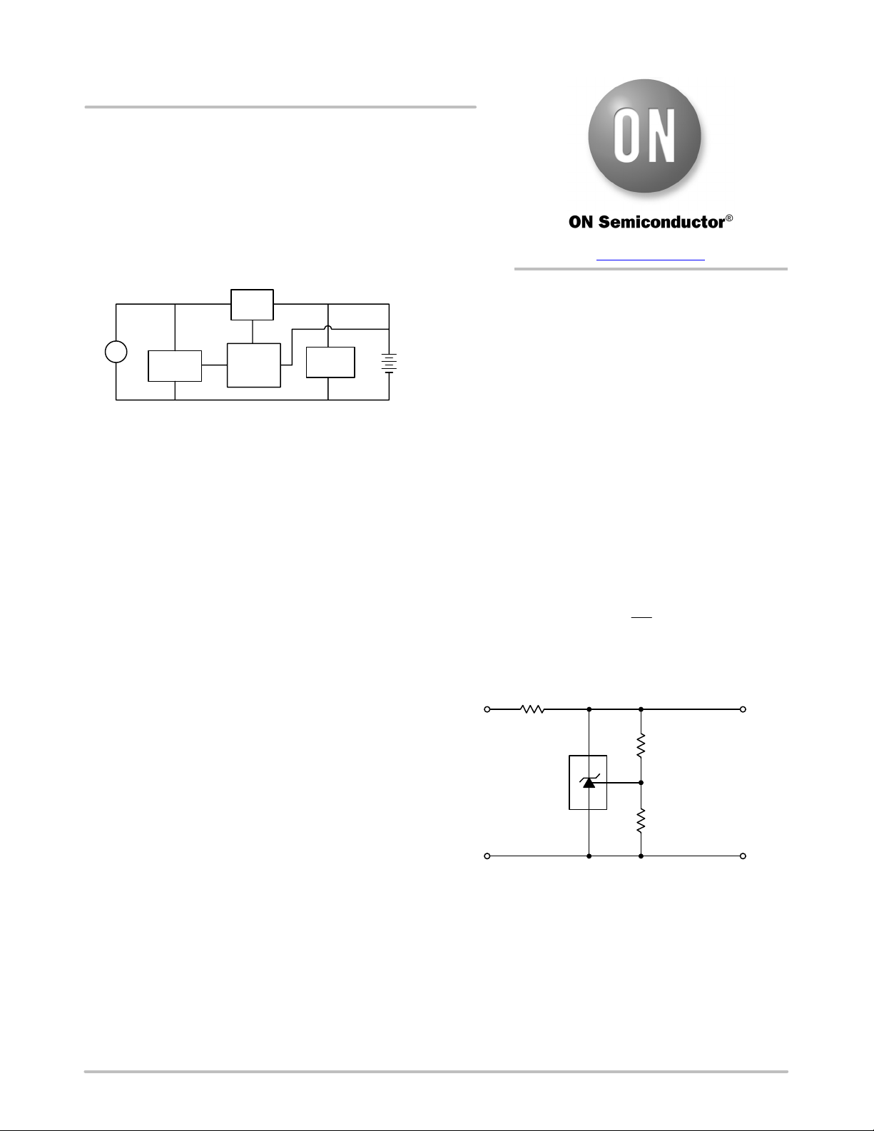
Setting the Reference Voltage
The TL431, a three-terminal programmable shunt
regulator, is used to set the reference voltage. It is designed
to give a constant 2.5 V output at its reference pin. When two
external resistors are connected as shown in Figure 2, the
reference voltage can be selected from 2.5 V to 36 V. For our
purposes we will set R
2
to 1.0 kW, and will adjust Rref to
match the reference voltage we want. The equation used to
find the ratio of R
2
/R
ref
is given by:
V
ref
+
ǒ
1 )
R
2
R
ref
Ǔ
2.5
The resistor that is connected to the cathode of the TL431
is used to limit the current, and to separate the input voltage
from the reference voltage.
Figure 2. Setup of Reference Voltage
V
ref
R
ref
R
2
R
1
V
+
Comparator with Hysteresis Loop
The LM311, a Single comparator, is used to compare the
voltage of the battery to the reference voltage. Connected to
the inverting input is the battery voltage. Hysteresis is
provided by a feedback resistor (R
h
) between the output and
the non-inverting input. R
3
, a 1.0 kW resistor is used to make
the ratio of R
3
/R
h
simple. By adjusting R
h
you can change
the bandwidth of the hysteresis loop. By increasing R
h
you
APPLICATION NOTE
www.onsemi.com