
下载
© Semiconductor Components Industries, LLC, 2009
December, 2009 − Rev. 1
1 Publication Order Number:
AND8431/D
AND8431/D
Designing a
Quasi-Resonant Adaptor
Driven by the NCP1380
Prepared by Stéphanie CONSEIL
ON Semiconductor
Quasi−square wave resonant converters also known as Quasi−Resonant (QR) converter are widely used in the adaptor
market. They allow designing flyback Switched−Mode Power Supply (SMPS) with reduced Electro−Magnetic Interference
(EMI) signature and improved efficiency. However, as the switching frequency of QR converter increases as the load decreases,
the frequency must be limited.
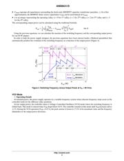
In traditional QR converter, the frequency is limited by a frequency clamp. But, when the switching frequency of the system
reaches the frequency clamp limit, valley jumping occurs: the controller hesitates between two valleys resulting in an unstable
operation and noise in the transformer at medium and light output loads.
In order to overcome this problem, the NCP1380 and the NCP1379 feature a “valley lockout” circuit: the switching
frequency is decreased step by step by changing valley as the load decreases. Once the controller selects a valley, it stays locked
in this valley until the output power changes significantly. This technique extends the QR operation of the system towards
lighter loads without degrading the efficiency.
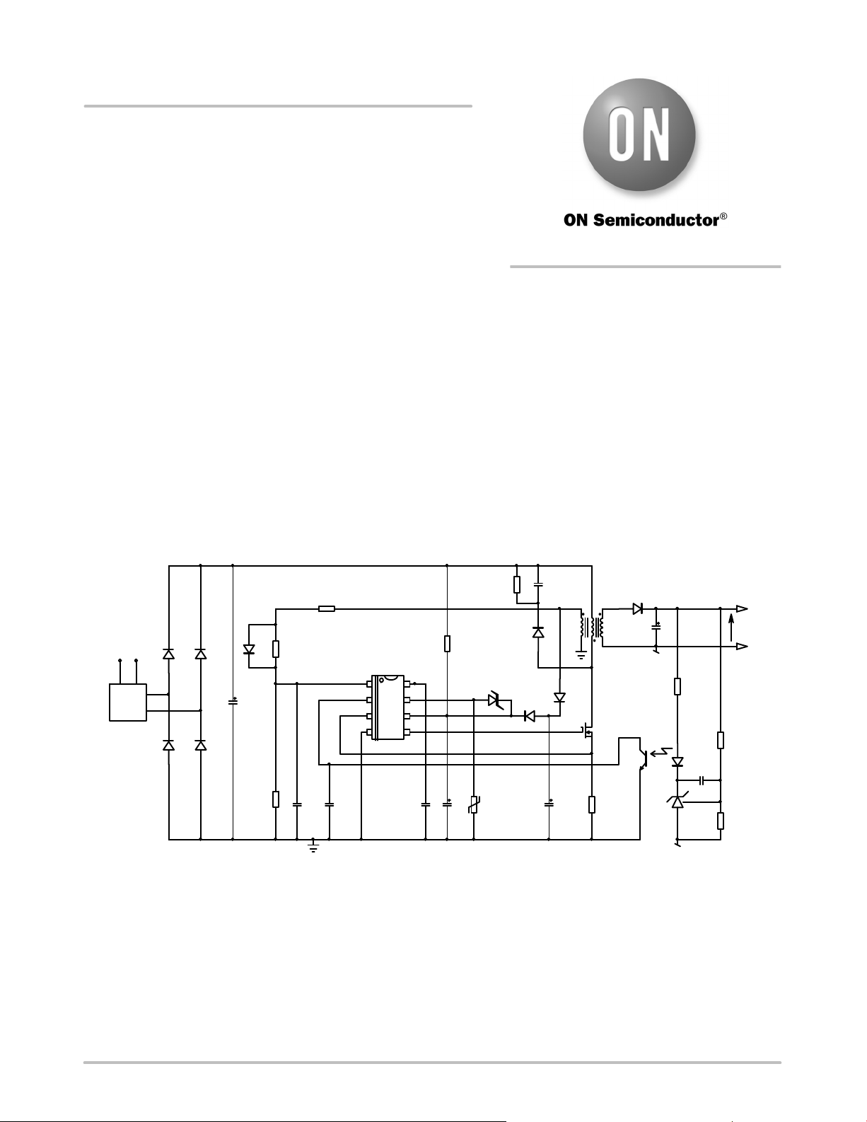
This application note focuses on the design of an adapter driven by the NCP1380. The equations developed are further used
to design a 60 W adapter. The same equations can be applied to the NCP1379.
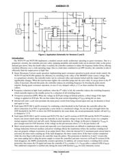
Figure 1. Application Schematic for Versions A and B
Vout
HV
−
b
u
lk
GND
GND
NCP1380 A/B
ZCD / OPP
1
2
3
45
8
6
7
EMI
Filter
Ac line
C
t
C
clamp
C
VCC1
C
fb
C
zcd
R
opu
R
opl
R
zcd
R
stup
R
sense
R
led
R
upper
R
lower
C
bulk
C
zero
R
clamp
OTP
OVP
D
1
D
clamp
M
1
C
out
C
VCC2
http://onsemi.com
APPLICATION NOTE