


下载

© Semiconductor Components Industries, LLC, 2010
March, 2010 − Rev. 1
1 Publication Order Number:
AND8373/D
AND8373/D
2 Switch-Forward Current
Mode Converter
Prepared by: Thierry Sutto
ON Semiconductor
Introduction
A major advantage of the two−switch forward converter
is that the power switches only block the supply voltage
instead of twice the supply voltage as in the flyback or
single−switch forward converter.
Here after, the complete specification, of the two
switch−forward converter is described:
Table 1. Specification
Description Value Units
Input voltage Range 350−410 Vdc
Output Voltage 12 Vdc
Output Power 96 W
Output Peak Power during 5 sec
per 1 min
120 W
Minimum Output Load Current(s) 0 Adc
Number of Outputs 1
Nominal Output Voltage 12
±5%
Vdc
Maximum Output Current 8 Adc
Maximum Output Peak Current 10 Adc
Output ripple 50 mV
Maximum startup time < 1 s
Standby Power < 100 mW
Target Efficiency at full load
@ Vin = 390 V dc
90 %
Load Conditions for Efficiency
Measurements (10%, 20%,..)
20, 50
& 100
%
Min Load Efficiency (Pout = 1.2 W) > 50 %
Maximum Transient load step of
the maximum output current
50 %
Maximum Output drop voltage from
I
out
= 5 to 10 A in 5 ms
250 mV
This application note describes the design of 120−W,
125 kHz, two−switch forward current mode converter with
the NCP1252 controller. It can viewed the practical
implementation of the 2−switch forward converter example
described in Ref. [1].
The NCP1252 controller offers everything to build
cost−effective and reliable ac−dc switching power supplies
implementing the forward converter: NCP1252 detects an
output overload without relying on the auxiliary Vcc, a
Brown−Out input offers protection against low input
voltages and improves the converter safety. Finally a SOIC8
package saves PCB space and represents a solution of choice
in cost sensitive projects.
The power supply described here operates from a dc input
voltage, as the forward converter is usually connected after
a Power Factor Correction (PFC) stage. It generates a 12−V
output at 10 A. The efficiency at full load is close to 90% at
the nominal output of the PFC.
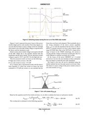
Power Supply Components Calculation
Transformer
The following equation extracted from the buck converter
running in Continuous Current Mode (CCM), turns ratio
will determine the turns ratio of the transformer:
V
out
+ h @ V
bulk min
@ DC
max
@ N
(eq. 1)
Where:
• V
out
is the output voltage
• h is the targeted efficiency
• V
bulkmin
is the minimum operating input voltage of the
forward
• DC
max
is the maximum duty cycle that the NCP1252
can deliver
• N is the turns ratio of the transformer
Extracting the turns ratio from the previous equation, we
obtain:
N +
V
out
hV
bulk min
DC
max
+
12
0.9 350 0.45
+ 0.085
(eq. 2)
http://onsemi.com
APPLICATION NOTE