
下载
© Semiconductor Components Industries, LLC, 2008
July, 2008 − Rev. 0
1 Publication Order Number:
AND8334/D
AND8334/D
Understanding Loop
Compensation with
Monolithic Switchers
Prepared by: Christophe Basso
ON Semiconductor
Introduction
Monolithic switchers, such as members of the NCP101X
or the NCP1027 series, associate a current-mode controller
and a power MOSFET on a single-die construction. Unlike
traditional solutions implementing an external sensing
resistor, these switchers embed everything inside the
package and can sometimes puzzle the power supply
designer looking for a familiar configuration. This
application note details what is inside these switchers and
will guide you on how to stabilize them using proven
compensation techniques.
Sensing the Inductor Current
All members of the NCP101X and NCP1027 series
implement the fixed-frequency peak current mode control
technique. This technique implies the cycle-by-cycle
sensing of the inductor current, its peak being controlled by
the feedback loop. The current information is usually
conveyed to the controller via a sensing element, the sense
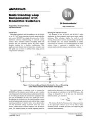
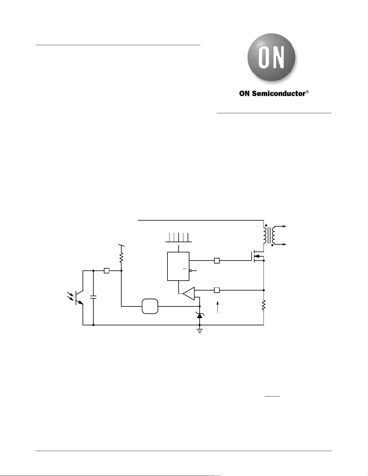
resistor. Figure 1 represents a simplified view of a
current-mode controller using an external sense resistor:
Figure 1. An External Sense Resistor Monitors the Current Circulating
in the Primary Inductor of this Flyback Power Supply
+
-
L
R
sense
Q
Q
R
S
DRV
CS
V
CS
dc rail
1 V
C
pole
FB
R
pullup
Vdd
clock
/ 3
The clock initiates a switching cycle by turning the
MOSFET on. The inductor current builds-up until it reaches
a level imposed by the feedback loop via the internal divider
by 3. At this point of time, the current sense comparator trips
and turns the MOSFET off until a new clock cycle occurs.
By adjusting the feedback level, the control loop has a means
to set the inductor peak current to cope with the input / output
operating conditions. A kind of active zener diode makes
sure the maximum voltage excursion across the sense
resistor cannot exceed a certain voltage in case the loop is
open. This happens during the startup sequence (until the
output reaches the target) or in short-circuit conditions. In
the vast majority of controllers, i.e. the NCP1200 series, this
voltage is clamped to 1 V. In that case, the maximum
inductor current I
L
is limited to:
I
L,peak
+
V
CS
R
sense
(eq. 1)
The internal divider by 3 increases the voltage excursion
on the optocoupler collector up to 3 V to offer a better
dynamics on the feedback pin while also improving the
converter noise immunity.
http://onsemi.com