
下载

Application Report
SLAA478–December 2010
Multi-Cell Li-Ion Battery Management System Using
MSP430F5529 and bq76PL536
Daniel Torres ............................................................................................... MSP430 System Solutions
ABSTRACT
This application report explains the implementation of a multi-cell lithium-ion battery management system
using an MSP430™ microcontroller and the bq76PL536. The battery manager is implemented using the
standard evaluation boards for the MSP430 MCU and the bq76PL536.
The bq76PL536 can be stacked vertically to monitor up to 192 cells without additional isolation
components between ICs. A high-speed serial peripheral interface (SPI) bus operates between each
bq76PL536 and the MSP430 microcontroller to provide reliable communications through a high-voltage
battery cell stack. The battery management system can communicate with an external host or battery
charger using USB communication or asynchronous serial communication such as RS232 or RS485.
This application report demonstrates the following features: passive cell balancing, cell undervoltage
monitor, cell overvoltage monitor, safety cell overvoltage monitor, cell overtemperature monitor. It also
detects whether the battery system is in charge or discharge mode by detecting changes of cell voltages.
Sample application code and other information associated with this application report can be downloaded
from http://www.ti.com/lit/zip/slaa478.
NOTE: This application note is applicable to all the MSP430 devices, the source code provided with
this document can be used as is with the MSP430F5xx family.
Contents
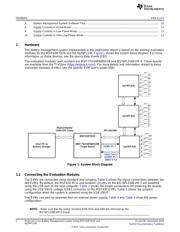
1 Hardware ..................................................................................................................... 2
2 Software ...................................................................................................................... 4
3 References ................................................................................................................. 11
Appendix A Benefits of the Ultra-Low-Power MSP430-Based Solution ................................................. 12
List of Figures
1 System Block Diagram..................................................................................................... 2
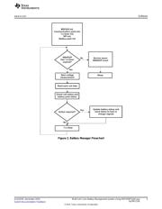
2 Battery Manager Flowchart................................................................................................ 5
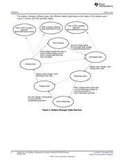
3 Battery Manager State Machine .......................................................................................... 6
4 Cell Charging Profile........................................................................................................ 7
5 Battery Pack Threshold Values ........................................................................................... 7
6 Cell Balancing Flowchart................................................................................................... 8
List of Tables
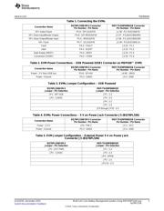
1 Connecting the EVMs ...................................................................................................... 3
2 EVM Power Connections – USB Powered (USB1 Connector on MSP430™ EVM)............................... 3
3 EVMs Jumper Configuration – USB Powered .......................................................................... 3
4 EVMs Power Connections – 5 V on Power Jack Connector J5 (BQ76PL536)..................................... 3
5 EVM Jumper Configuration – External Power 5 V on Power Jack Connector J5 (BQ76PL536)................. 3
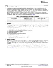
6 Asynchronous Serial Port (UART) Connections ........................................................................ 4
MSP430 is a trademark of Texas Instruments.
1
SLAA478–December 2010 Multi-Cell Li-Ion Battery Management System Using MSP430F5529 and
bq76PL536
Submit Documentation Feedback
© 2010, Texas Instruments Incorporated