


下载
MRF8P8300HR6 MRF8P8300HSR6
1
RF Device Data
Freescale Semiconductor, Inc.
RF Power Field Effect Transistors
N--Channel Enhancement--Mode Lateral MOSFETs
Designed for W--CDMA and LTE base station applications with frequencies
from 750 to 820 MHz. Can be used in Class AB and Class C for all typic al
cellular base station modulation formats.
Typical Single--Carrier W--CDMA Performance: V
DD
=28Volts,I
DQ
=
2000 mA, P
out
= 96 Watts Avg., IQ Magnitude Clipping, Channel
Bandwidth = 3.84 MHz, Input Signal PAR = 7.5 dB @ 0.01% Probability
on CCDF.
Frequency
G
ps
(dB)
D
(%)
Output PAR
(dB)
ACPR
(dBc)
790 MHz 20.9 35.2 6.2 --38.1
805 MHz 21.0 35.5 6.2 --38.1
820 MHz 20.9 35.7 6.1 --38.2
Capable of Handling 10:1 VSWR, @ 32 Vdc, 805 MHz, 500 Watts CW Output
Power (3 dB Input Overdrive from Rated P
out
), Designed for
Enhanced Ruggedness
Typical P
out
@ 1 dB Compression Point ≃ 340 Watts CW
Features
100% PAR Tested for Guaranteed Output Power Capability
Characterized with Series Equivalent Large--Signal Impedance Parameters
and Common Source S--Parameters
Internally Matched for Ease of Use
Integrated ESD Protection
Greater Negative Gate--Source Voltage Range for Improved Class C
Operation
Designed for Digital Predistortion Error Correction Systems
Optimized for Doherty Applications
In Tape and Reel. R6 Suffix = 150 Units, 56 mm Tape Width, 13--inch Reel.
Table 1. Maximum Ratings
Rating Symbol Value Unit
Drain--Source Voltage V
DSS
--0.5, +70 Vdc
Gate--Source Voltage V
GS
--6.0, +10 Vdc
Operating Voltage V
DD
32, +0 Vdc
Storage Temperature Range T
stg
--65 to +150 C
Case Operating Temperature T
C
150 C
Operating Junction Temperature
(1,2)
T
J
225 C
Table 2. Thermal Characteristics
Characteristic Symbol Value
(2,3)
Unit
Thermal Resistance, Junction to Case
Case Temperature 80C, 96 W CW, 28 Vdc, I
DQ
= 2000 mA, 820 MHz
Case Temperature 85C, 300 W CW, 28 Vdc, I
DQ
= 2000 mA, 820 MHz
R
JC
0.26
0.21
C/W
1. Continuous use at maximum temperature will affect MTTF.
2. MTTF calculator available at http://www.freescale.com/rf
. Select Software & Tools/Development Tools/Calculators to access MTTF
calculators by product.
3. Refer to AN1955, Thermal Measurement Methodology of RF Power Amplifiers. Go to http://www.freescale.com/rf
.
Select Documentation/Application Notes -- AN1955.
Document Number: MRF8P8300H
Rev. 1, 4/2013
Freescale Semiconductor
Technical Data
750--820 MHz, 96 W AVG., 28 V
SINGLE W--CDMA
LATERAL N--CHANNEL
RF POWER MOSFETs
MRF8P8300HR6
MRF8P8300HSR6
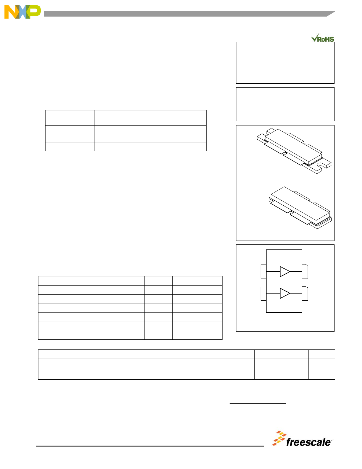
NI--1230--4H
MRF8P8300HR6
NI--1230--4S
MRF8P8300HSR6
(Top View)
RF
outA
/V
DSA
31
42
RF
outB
/V
DSB
RF
inA
/V
GSA
RF
inB
/V
GSB
Figure 1. Pin Connections
Freescale Semiconductor, Inc., 2011, 2013.
A
ll rights reserved.