

下载
© Freescale Semiconductor, Inc., 2005. All rights reserved.
AN1082
Rev 4, 05/2005
Freescale Semiconductor
Application Note
Simple Design for a 4-20 mA Transmitter
Interface Using a Pressure Sensor
by: Jean Claude Hamelain
Toulouse Application Lab Manager
INTRODUCTION
Pressure is a very important parameter in most industrial
applications such as air conditioning, liquid level sensing and
flow control.
In most cases, the sensor is located close to the measured
source in a very noisy environment, far away from the receiver
(recorder, computer, automatic controller, etc.)
The transmission line can be as long as a few hundred
meters and is subject to electromagnetic noise when the
signal is transmitted as voltage. If the signal is transmitted as
a current it is easier to recover at the receiving end and is less
affected by the length of the transmission line.
The purpose of this note is to describe a simple circuit
which can achieve high performance, using standard pressure
sensors, operational amplifiers and discrete devices.
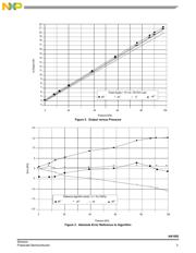
PERFORMANCES
The following performances have been achieved using an
MPXV2102DP pressure sensor and an MC33079 quad
operational amplifier. The MPXV2102DP is a 100 kPa
temperature compensated differential pressure sensor. The
load is a 150 ohm resistor at the end of a 50 meter telephone
line. The 15 volt power supply is connected at the receiver
end.
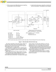
Basic Circuit
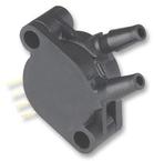
The MPXV2102DP pressure sensor is a very high
performance piezoresistive pressure sensor. Manufacturing
technologies include standard bipolar processing techniques
with state of the art metallization and on-chip laser trim for
offset and temperature compensation.
This unique design, coupled with computer laser trimming,
gives this device excellent performance at competitive cost for
demanding applications such as automotive, industrial or
healthcare.
MC33078, 79 operational amplifiers are specially designed
for very low input voltage, a high output voltage swing and
very good stability versus temperature changes.
First Stage
The MPXV2102 and the operational amplifier are directly
powered by the 15 Vdc source. The first stage is a simple true
differential amplifier made with both of the operational
amplifiers in the MC33078. The potentiometer, R
G
, provides
adjustment for the output.
Current Generator
The voltage to current conversion is made with a unity gain
differential amplifier, one of the four operational amplifiers in
an MC33079. The two output connections from the first stage
are connected to the input of this amplifier through R3 and R5.
Good linearity is achieved by the matching between R3, R4,
R5 and R6, providing a good common mode rejection. For the
same reason, a good match between resistors R8 and R9 is
needed.
The MC33078 or MC33079 has a limited current output;
therefore, a 2N2222 general purpose transistor is connected
as the actual output current source to provide a 20 mA output.
To achieve good performance with a very long transmission
line it may be necessary to place some capacitors (C1, C2)
between the power supply and output to prevent oscillations.
Calibration
The circuit is electrically connected to the 15 Vdc power
supply and to the load resistor (receiver).
The high pressure is connected to the pressure port and the
low pressure (if using a differential pressure sensor), is
connected to the vacuum port.
It is important to perform the calibration with the actual
transmission line connected.
The circuit needs only two adjustments to achieve the 4-
20mA output current.
Power Supply +15 Vdc, 30 mA
Connecting Line 3 wire telephone cable
Load Resistance 150 to 400 Ohms
Temperature Range -40 to +85°C (up to +125°C with special
hardware)
Pressure Range 0 to 100 kPa
Total Maximum Error Better than 2% full scale