

下载

© 2015 Freescale Semiconductor, Inc. All rights reserved.
Features of the FlexTimer Module
1. Introduction
The application note introduces multiple features of the
FlexTimer Module (FTM) and provides corresponding
code for each feature, along with a waveform or a
snapshot of the oscilloscope. While FTM is used in both
the Kinetis and Vybrid families, this application note
focuses on Kinetis only.
FTM is available for all of the Kinetis K series. FTM is
an enhanced version of the Timer/PWM module (TPM)
of HCS08 with new features.
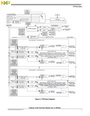
FTM can:
• function as the Timer and Pulse Width
Modulation (PWM) signal generator,
• generate at most eight PWM signals for each
FTM module, and
• generate edge-aligned PWM signals, center-
aligned PWM signals, and phase-shift PWM
signals.
External/internal fault signals can disable PWM output
signal. The PWM module can trigger ADC directly or
through the PDB module. FTM can generate four pairs
of complementary PWM signal for edge-aligned, center-
aligned, and phase shift PWM signals.
FTM also has masking, inverting, and software
controlling function for BLDC motor control application.
The features described in this application note are
applicable for BLDC/ACIM/PMSM/SR motor control or
switch mode power supply applications.
Freescale Semiconductor, Inc.
Document Number: AN5142
Application Notes
Rev. 0
,
06/2015
Contents
1. Introduction ........................................................................ 1
2. FTM description ................................................................. 2
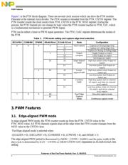
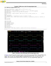
3. PWM Features .................................................................... 4
3.1. Edge-aligned PWM mode ....................................... 4
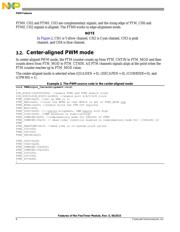
3.2. Center-aligned PWM mode ..................................... 6
3.3. Complementary PWM signal .................................. 7
3.4. Phase-shift PWM signal (Combined PWM signals
or Asymmetric PWM signal) ................................................. 8
3.5. Divider .................................................................. 10
3.6. Generating a fixed cycle time interrupt ................. 10
3.7. FTM triggering ADC ............................................ 11
3.8. Single-edge capture mode ..................................... 14
3.9. Dual-edge capture mode ........................................ 15
3.10. Quadrature decoder mode ..................................... 17
3.11. Updating the FTM registers................................... 19
3.12. Masking, inverting, and software controlling
features ……………………………………………………26
3.13. Fault signal disabling PWM output signals ........... 27
3.14. Multiple FTM synchronization .............................. 29
3.15. FTM channel initial logic ...................................... 32
3.16. PWM resolution .................................................... 32
Appendix A. Pin assignment code ....................................... 34
4. Revision history ................................................................ 35