

下载
ã
1998 Microchip Technology Inc. DS00686A-page 1
M
AN686
SCOPE
This application note discusses what microcontroller
supervisory devices are, why they are needed and
some factors to consider when choosing one. Supervi-
sory devices is a broad term that encompasses POR
(power on reset) devices, BOD (brown-out detect)
devices and watchdog timer devices. This application
note will cover supervisor devices with POR and BOD
functions only.
WHAT DOES A SUPERVISORY
CIRCUIT DO?
A supervisory circuit can be used for several different
applications, but there are two primary functions that a
supervisor provides:
1. During a power up sequence, the device holds a
microcontroller in reset until the system power
has come up to the correct level and stabilized
(the POR function), and
2. reset the controller immediately if the power
drops below a nominal value either at power
down or during a ‘brown-out’ condition.
Some supervisor devices also provide things like low
battery warning, watchdog timer and other more elab-
orate functions that are beyond the scope of this appli-
cation note.
WHY DO I NEED A SUPERVISORY
CIRCUIT ANYWAY?
One question system designers may ask themselves
is, “Why do I need one of these things anyway?” There
are 3 situations that you must consider when answer-
ing this question:
3. What would happen to the microcontroller (or
other devices in the system) if there was noise
on the supply voltage as it powers up?
4. What would happen if there is a glitch on the
power supply while the system is running?
5. What does the microcontroller do when the sys-
tem power is turned off?
If you ponder these questions and have visions of
phone calls from angry customers, then you might con-
sider using a supervisor device.
In the Beginning: Power-Up Problems
Most designers working on a prototype system are
familiar with putting a reset switch of some kind on the
reset pin of the microcontroller. Why? Because they are
making both hardware and firmware changes, which-
sometimes cause the system to malfunction, resulting
in the microcontroller no longer behaving in a rational
manner. Sometimes it just plain doesn’t work. The sys-
tem designer pushes the reset button a couple of times
to determine if the problem goes away. If not, more
changes are made and the process continues. The
push button provides a means of manually resetting the
system. This may work fine for the system development
phase, but what do you do to ensure proper system
power-up when it goes into production?
Many systems rely on a simple pullup resistor tied to
the reset line and their system works fine every time.
But what if different components in the system are all
powering up as the supply voltage is ramping up and
noise is injected onto the supply line? Most microcon-
trollers have specs that describe power up ramps for
proper initialization of the controller. A glitch on the sup-
ply line may very well cause the microcontroller (or
some other component) to power-up incorrectly and
prevent the system from operating as intended. See
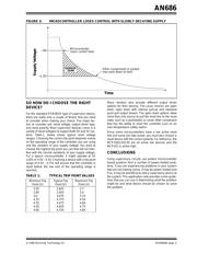
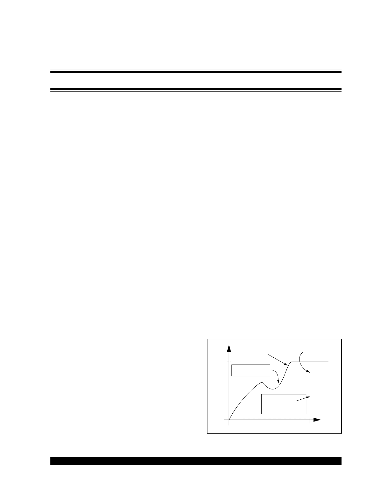
Figure 1. A supervisor device solves this problem by
holding the microcontroller in reset until the power has
reached a stable level. Timeout periods vary for differ-
ent devices but typical values are 150ms - 500ms.
When the timeout period is complete, the device will
release the reset line and allow the microcontroller to
begin exection of its code.
FIGURE 1: POR FUNCTION
0
Time
Voltage
0
500ms
5V
Supervisor holds
microcontroller in
reset until the supply
voltage is stable
Possible glitch in
power supply ramp
Supervisor
Output
Pin
Supply
Voltage
Understanding and Using Supervisory Circuits