
下载
1998-2011 Microchip Technology Inc. DS00682D-page 1
AN682
INTRODUCTION
Beyond the primitive transistor, the operational ampli-
fier (op amp) is the most basic building block for analog
applications. Fundamental functions such as gain, load
isolation, signal inversion, level shifting, adding and/or
subtracting signals are easily implemented with an op
amp. More complex circuits can also be implemented,
such as the instrumentation amplifier, a current-to-volt-
age converter, and filters, to name only a few. Regard-
less of the level of complexity of the op amp circuit,
knowing the fundamental operation and behavior of an
op amp will save a considerable amount of up-front
design time.
Formal classes on this subject can be very comprehen-
sive and useful. However, many times they fall short in
terms of experience or common sense. For instance, a
common mistake that is made when designing with op
amps is neglecting to include bypass capacitors in the
circuit. Op amp theory often overlooks this practical
detail. If the bypass capacitor is missing, the amplifier
circuit can oscillate at a frequency that “theoretically”
doesn’t make sense. If textbook solutions are used, this
can be a difficult problem to solve.
This application note is divided into three sections. The
first section lists fundamental amplifier applications,
including design equations. These amplifier circuits
were selected with embedded system integration in
mind.
The second section uses these fundamental circuits to
build useful amplifier functions in embedded control
applications.
The third section identifies the most common single-
supply op amp circuit design mistakes. This list of mis-
takes has been gathered over many years of trouble-
shooting circuits with numerous designers in the
industry. The most common design pitfalls can easily
be avoided if the suggestions in this application note
are used.
FUNDAMENTAL OP AMP CIRCUITS
The op amp is the analog building block that is analo-
gous to the digital gate. By using the op amp in the
design, circuits can be configured to modify the signal
in the same fundamental way that the inverter and the
AND and OR gates do in digital circuits. In this section,
fundamental building blocks such as the voltage fol-
lower, non-inverting gain and inverting gain circuits are
discussed, followed by a rail splitter, difference
amplifier, summing amplifier and the current-to-voltage
converter.
Voltage Follower Amplifier
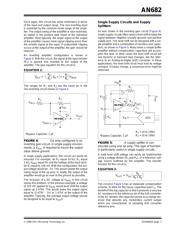
Starting with the most basic op amp circuit, the buffer
amplifier (shown in Figure 1) is used to drive heavy
loads, solve impedance matching problems, or isolate
high power circuits from sensitive, precise circuitry.
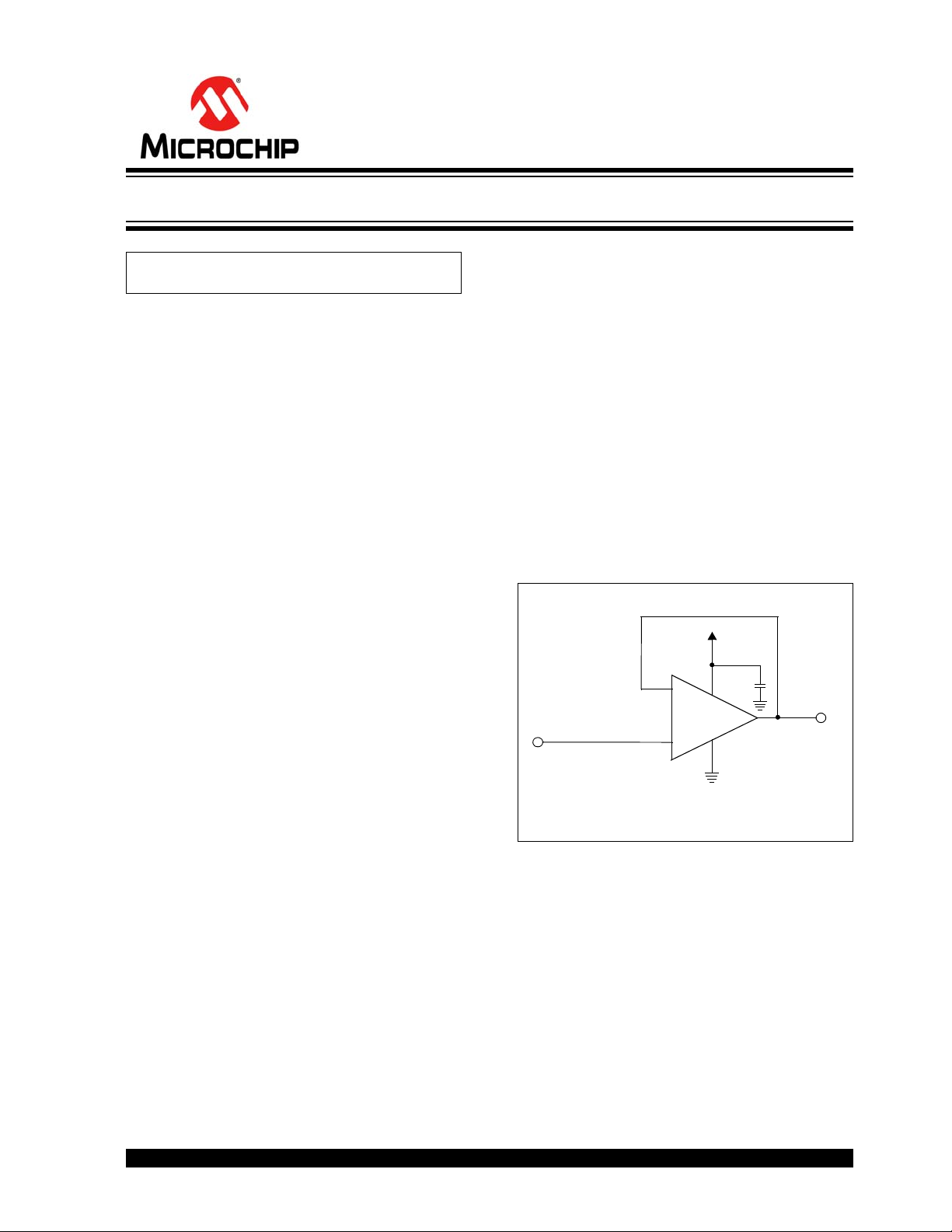
FIGURE 1: Buffer amplifier; also called a
voltage follower.
The buffer amplifier shown in Figure 1 can be imple-
mented with any single-supply, unity-gain, stable ampli-
fier. In this circuit, as with all amplifier circuits, the op
amp must be bypassed with a capacitor. For single-
supply amplifiers that operate in bandwidths from DC to
megahertz, a 1 µF capacitor is usually appropriate.
Sometimes a smaller bypass capacitor is required, for
amplifiers that have bandwidths up to the 10s of mega-
hertz. In these cases, a 0.1 µF capacitor would be
appropriate. If the op amp does not have a bypass
capacitor or the wrong value is selected, it may
oscillate.
Author: Bonnie Baker
Microchip Technology Inc.
MCP601
V
OUT
= V
IN
*Bypass Capacitor, 1 µF
*
2
7
3
4
6
V
OUT
V
DD
V
IN
–
+
Using Single Supply Operational Amplifiers in Embedded Systems