

下载
2004 Microchip Technology Inc. DS00737C-page 1
M
AN737
INTRODUCTION
The most common filter found in a data acquisition
system signal path is a low-pass filter. This type of filter
is usually used to reduce A/D Converter (ADC) aliasing
errors. If there is more than one signal that is applied to
the A/D converter through a multiplexer, each signal
source may have its own set of filter requirements (i.e.,
settling time, fast transition region, etc.). Consequently,
a variety of filters may be required in the circuit prior to
the multiplexer. Usually these filters are implemented
with operational amplifiers (op amps) in combination
with fixed resistors and capacitors.
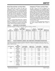
An alternative filter design solution is to have one filter
following the multiplexer. In this circuit, the low-pass
filter would need to be programmable. The obvious
advantage of having the filter serve many analog inputs
is that there is a reduction in chip count. An example of
this type of approach is shown in Figure 1.
FIGURE 1: If a programmable low-pass
filter is used in the application circuit, it can be
placed after the analog multiplexer. The
programmability of the filter allows for a wide vari-
ety of input signals.
Programmable Low-Pass Filters
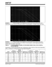
In this application note, a programmable, second-
order, low-pass filter will be presented in four different
scenarios. The first three scenarios will illustrate how a
dual digital potentiometer and a single amplifier can be
configured for low-pass second-order Butterworth,
Bessel and Chebyshev responses with a programma-
ble corner frequency range of 1:100. An example of the
digital potentiometer setting for these designs is
summarized in Tables 1, 2 and 3. The fourth scenario
will show the same circuit design, where all three
approximation methods (Butterworth, Bessel and
Chebyshev) can coexist with a programmable corner
frequency range of 1:10. An example of the digital
potentiometer settings for this combination of
approximation methods is summarized in Table 4.
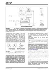
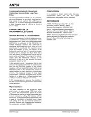
Figure 2 shows the details of a single-supply, unity
gain, second-order, programmable low-pass Sallen
Key filter. This filter is implemented with two resistors
and two capacitors. The two resistors in this circuit are
replaced with the dual MCP42100, 100 kΩ, 8-bit, digital
potentiometer.
FIGURE 2: The combination of a dual
digital potentiometer and a single-supply, rail-to-
rail amplifier can be used to construct a program-
mable, second-order, Sallen-Key, low-pass filter.
Digital potentiometers can be used to adjust system
reference levels, gain errors and offset errors, while
offering the added capability of digital adjustment
control. Devices such as Microchip’s MCP41XXX and
MCP42XXX digital potentiometer families have three
resistive terminals for the single versions (MCP41010,
MCP41050 and MCP41100) and six resistive terminals
for the dual versions (MCP42010, MCP42050 and
MCP42100) and are illustrated in Figure 3. The
MCP41010 and MCP42010 are both 10 kΩ
potentiometers. The MCP41050 and MCP42050 are
both 50 kΩ potentiometers, while the MCP41100 and
42100 are both 100 kΩ potentiometers.
Author: Bonnie C. Baker
Microchip Technology Inc.
Analog
Multiplexer
Programmable
Low-Pass
Filter
12-bit
A/D Converter
Temperature 1
Vibration
Pressure
Temperature 2
Temperature 3
Acceleration
+
-
V
IN
V
OUT
C
1
C
2
R
1
MCP601
MCP3201
12-bit ADC
1/2
100 kΩ Digital
Potentiometers
Single-Supply,
Rail-to-Rail Input
Op Amp
P
A1
P
W1
P
B1
MCP42100
1/2
MCP42100
P
A0
P
W0
P
B0
R
2
Using Digital Potentiometers to Design
Low-Pass Adjustable Filters