

下载

2010 Microchip Technology Inc. DS01316A-page 1
AN1316
INTRODUCTION
Usually a sensor requires its output signal to be
amplified before being converted to a digital
representation. Many times an operational amplifier (op
amp) is used to implement a signal gain circuit. The
programmability of this type of circuit allows the
following issues to be solved:
• Optimization of the sensor output voltage range
• Calibration of the amplifier circuit’s gain
• Adapting gain to input signal variations
- sensor characteristics change over
temperature/voltage
- multiple input sources into a single gain
circuit
• Field calibration updates
• Increased reliability vs mechanical potentiometer
• BOM consolidation – one op amp and one digital
potentiometer supporting the various sensor
options
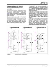
This Application Note will discuss implementations of
programmable gain circuits using an op amp and a dig-
ital potentiometer. This discussion will include imple-
mentation details for the digital potentiometer’s resistor
network. It is important to understand these details to
understand the effects on the application.
OVERVIEW OF AMPLIFIER GAIN
CIRCUIT
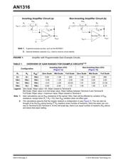
Figure 1 shows two examples of amplifier circuits with
programmable gain. Circuit “a” is an inverting amplifier
circuit, while circuit “b” is a non-inverting amplifier
circuit.
In these circuits, R
1
, R
2
and Pot
1
are used to tune the
gain of the amplifier. The selection of these
components will determine the range and the accuracy
of the gain programming.
The inverting amplifier’s gain is the negative ratio of
(R
2
+ R
BW
)/(R
1
+ R
AW
). The non-inverting amplifier’s
gain is the ratio of ((R
2
+ R
BW
)/(R
1
+ R
AW
) + 1). The
feedback capacitor (C
F
) may be used if additional
circuit stability is required.
These circuits can be simplified by removing resistors
R
1
and R
2
(R
1
= R
2
= 0) and just using the digital
potentiometers R
AW
and R
BW
ratio to control the gain.
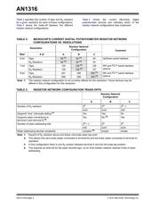
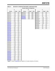
The simplified circuit reduces the cost and board area
but there are trade-offs (for the same resistance and
resolution). Ta ble 1 shows some of the trade-offs with
respect to the gain range that can be achieved, where
the R
AB
resistance is the typical R
AB
value and the R
1
and R
2
resistance values are varied. A more detailed
discussion is included later in this Application Note.
Using a general implementation, the R
1
and R
2
resistors allow the range of the gain to be limited;
therefore, each digital potentiometer step is a fine
adjust within that range. While in the simplified circuit,
the range is not limited, so each digital potentiometer
step causes a larger variation in the gain.
One advantage of the simplified circuit is that the R
BW
and R
AW
resistors are of the same material so the
circuit has a very good temperature coefficient
(tempco). While in the general circuit, the tempco of the
R
1
and R
2
devices may not match each other or the
digital potentiometer device.
Author: Mark Palmer
Microchip Technology Inc.
Using Digital Potentiometers for
Programmable Amplifier Gain