

下载
2004 Microchip Technology Inc. DS00692B-page 1
M
AN692
INTRODUCTION
Photodiodes bridge the gap between light and
electronics. Many times, precision applications (such
as CT scanners, blood analyzers, smoke detectors,
position sensors, IR pyrometers and chromatographs)
utilize the basic transimpedance amplifier circuit that
transforms light energy into a usable electrical voltage.
In these circuits, photodiodes are used to capture the
light energy and transform it into a small current. This
current is proportional to the level of illumination from
the light source. A preamplifier then converts the
current (in amperes) from the photodiode sensor into a
usable voltage level.
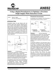
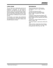
FIGURE 1: In this precision
photosensing configuration, a photodiode (in the
Photovoltaic mode) is used to capture the
luminance energy from a light source. The effects
of the variability, due to alignment problems, is
reduced by using a potentiometer for the resistive
element in the feedback loop of the amplifier.
This application note will show how the adjustability of
the digital potentiometer can be used as an advantage
in photosensing circuits. Initially, photodiode
characteristics will be looked at, followed by various
digital potentiometer circuits that use photodiodes in
the Photoconductive and Photovoltaic modes.
Photodiode Characteristics
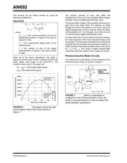
A photodiode can be operated in the Photovoltaic or
Photoconductive mode, as shown in Figure 2.
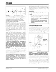
FIGURE 2: The two modes that
photodiodes can be used in are: (a) Photovoltaic
and (b) Photoconductive. In the Photovoltaic
mode, the photodiode is biased with zero volts
which optimizes the sensor’s accuracy. In the
Photoconductive mode, the diode is reverse
biased in order to optimize the responses to step
functions.
A photodiode configured in the Photovoltaic mode is
zero biased. In this mode, the light-to-current response
of the diode is maximized for light sensitivity and
linearity, making it well suited for precision applications.
A photodiode configured in the Photoconductive mode
has a reverse voltage bias applied. In this mode, the
photodiode is optimized for fast response to light
sources. An ideal application for a diode configured in
the Photoconductive mode is digital communication.
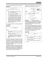
The key elements that influence the circuit
performance of each mode are the photodiode
capacitance (C
PD
) and the photodiode leakage current
(I
L
), as shown in Figure 3. These parasitic elements
can effect the precision and speed of photo detection
circuits.
Author: Bonnie C. Baker
Microchip Technology Inc.
Light
V
OUT
R
F
I
SC
+5V
MCP601
Source
V
OUT
= +I
SC
R
F
-V
BIAS
Light
Source
Light
Source
b) Photodiode
configured in
Photoconductive mode
a) Photodiode
configured in
Photovoltaic mode
Using a Digital Potentiometer to Optimize a Precision
Single-Supply Photo Detection Circuit