


Maxim > Design Support > Technical Documents > Application Notes > Amplifier and Comparator Circuits > APP 4840
Maxim > Design Support > Technical Documents > Application Notes > Battery Management > APP 4840
Keywords: load switching, rechargeable battery-powered systems, Li+ battery chargers, power OK (POK)
outputs
APPLICATION NOTE 4840
Battery/Charger Load Switch Approximates Ideal
Diode
By: Budge Ing
Hubert Bugajski
Feb 10, 2011
Abstract: Two circuits are described. The first uses external MOSFETs driven by the Power OK (POK)
output of a Li-cell charger IC (MAX8814), to switch a load between battery and charging source without
intervention from a microcontroller or system software. For charger ICs without a POK output (such as
the MAX1507), the second circuit does the same switching using MOSFETs and a comparator
(MAX920).
A similar version of this article appeared in the July 19, 2010 issue of Electronic Design magazine.
Most rechargeable battery-powered systems include a switch that connects the load either to the battery
or to a source of charging power. Without it, a system with depleted battery may not operate
immediately when plugged in. A switching circuit also allows the system to operate on adapter power
while the battery is charging.
The simplest and lowest-cost method for this battery/adapter power handoff is a diode-OR connection.
The load connects to each power source (battery and adapter) through separate Schottky diodes, so
power is applied by the higher voltage—battery or adapter. The drawback to this approach is the power
loss (P
D
= I
BATTERY
V
DIODE
) and voltage drop (V
DIODE
= 0.350V at 0.5A, from the PMEG2010AEH data
sheet) incurred when the battery services the load. Such losses may not be significant for high-voltage
multicell batteries, but for 1-cell Li+ batteries or 2–4 cell NiMh batteries, the percentages of power loss
and diode drop across the blocking diode are considerable.
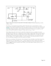
The circuit of Figure 1 switches loads with a voltage drop of only 45mV at 0.5A, which is a head-room
improvement of 350mV - 45mV = 305mV. When compared with the diode-OR connection (175mW vs.
22.5mW), the power saving is 152.5mW. At lower currents the dropout voltage is even lower. At 100mA,
for instance, a diode drops about 270mV but the Figure 1 circuit drops only 10mV.
Page 1 of 4