


下载

Maxim > Design Support > Technical Documents > Application Notes > Amplifier and Comparator Circuits > APP 3983
Maxim > Design Support > Technical Documents > Application Notes > Power-Supply Circuits > APP 3983
Keywords: resonant- reset, forward converter, single-transistor, sinusoidal reset, synchronous-rectifier
APPLICATION NOTE 3983
Designing Single-Switch, Resonant-Reset,
Forward Converters
By: Suresh Hariharan, Director and Product Definer
Mar 20, 2007
Abstract: Among power-converter topologies, the single-transistor, forward converter is one of the most
common for power levels below 100 watts. This article describes an improvement to that circuit called the
"single-transistor, resonant-reset, forward converter," which eliminates the reset winding and a diode
(D
TR
). Several other advantages of this design will be discussed.
A similar article appeared in the October 2005 issue of Power Electronics Technology.
Introduction
Single-transistor, resonant-reset forward converters are commonly used in DC-DC converter modules for
power levels below 100 watts. These devices are also quite useful for DC-DC converters with widely
adjustable output voltages. This article, however, describes an improved circuit called the "single-
transistor resonant-reset forward converter." This design eliminates the reset winding and a diode (D
TR
),
and offers several distinct advantages.
The duty cycle for this resonant-reset converter can exceed 50%, making it suitable for low-cost DC-DC
converters that operate from wide input voltages and deliver widely varying outputs. The absence of a
reset winding reduces costs by simplifying the transformer, especially for the planar transformers widely
used in high-density DC-DC converter modules. Finally, the resonant-reset circuit's sinusoidal reset
voltage reduces EMI.
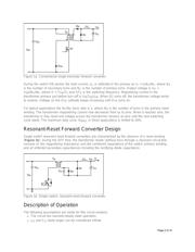
Conventional Single-Switch Forward Converter Design
To properly appreciate the resonant-reset topology, we must first understand the conventional single-
switch forward converter (Figure 1a). When switch Q1 turns on, the transformer current rises from zero
and the diode, D
TR
, is reverse biased. Transformer magnetizing current builds up to a value I
M
=
V
IN
T
ON
/L
M
, where T
ON
is the ON time per switching cycle and L
M
is the magnetizing current.
Page 1 of 10