下载

Maxim > Design Support > Technical Documents > Application Notes > Hot-Swap and Power Switching Circuits > APP 2018
Keywords: Protection From Blackouts: Dirt Cheap to Fully Integrated
APPLICATION NOTE 2018
Protection From Blackouts: Dirt Cheap to Fully
Integrated
May 11, 2003
Abstract: Consider a scenario that is all too common: Far along in the process of developing a peripheral
that will interface with the USB port of a PC, the designer takes up the problem of how it should be
powered. This power source can pose a problem, because the peripheral must operate when the PC is
shut down as well as when it is up and running.
It makes sense to obtain power from the PC's USB port, but that approach allows operation only when
the PC is running. Another obvious solution is a standard 110VAC outlet and an ac-dc converter, but that
source exposes the device to the noise and voltage fluctuations inherent in any ac outlet. Thus, an
alkaline or rechargeable battery, though not practical as the sole power source, is a necessary
component if the peripheral is to be portable. A third option is to make use of all three power sources.
Though sacrificing simplicity, that arrangement makes the product more versatile, and it is not as difficult
or as costly as one might think.
Circuitry for switching between the adapter and USB portcan be as simple as a MOSFET and diode, or
as complex as two power converters. Either case requires a battery, both for backup and to enable
portable operation. The following discussion introduces different ways to utilize the advantages of all
three power sources. Each option has pros and cons, but each gets the job done.
Dirt Cheap
A diode, a FET, and a resistor are all it takes to build a basic switchover circuit. The input stage of
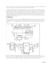
Figure 1 shows how the circuit accomplishes seamless switching between the USB port and the adapter.
As voltage on the USB supply line drops, the FET connects the +5V adapter to the battery charger.
Under a load of 250mA, this connection occurs when the USB voltage drops to +4.3V.
For Larger Image
Figure 1. This simple circuit accomplishes power-supply switchover with seamless switching, but runs the
risk of connecting both supplies at once.
A low component count makes this topology quite reliable, and also simplifies any necessary debugging
and failure analysis. The circuit provides +1.25V to +5V at up to 600mA, with 95% efficiency. The backup
Page 1 of 6

