


下载

Maxim > Design Support > Technical Documents > Application Notes > Battery Management > APP 665
Keywords: ccd, charge coupled devices, smps, power conversion, transformer, flyback, power converter,
snubber
APPLICATION NOTE 665
Flyback Converter Serves Battery-Powered CCD
Applications
By: Bob Kelly, Senior Applications Engineer
Jan 31, 2001
Abstract: This article describes the design of a flyback power converter to operate CCD equipment such
as digital cameras from four AAA cells. The MAX752 and a multiple output transformer deliver +15V, -
7.5V and 5V. First pass design had low efficiency at low input voltages, and large voltage spikes on the
Lx pin. MOSFET operation is improved at low voltage with diodes. Flyback spikes due to non-ideal
transformer action are controlled with a snubber network. Efficiency curve shows greater than 80% with
a 50-ohm load and 5.25V input. The MAX752 operates at 170kHz. Input voltage range is 3.5V to 6.5V.
A flyback power supply can produce multiple voltages to support products that use charge-coupled
devices for imaging.
Products that use charge-coupled devices (CCDs) for imaging require multiple-power-supply voltages,
such as 15V, -7.5V, and 5V. A power-supply circuit for generating these voltages has a power source of
four AAA alkaline cells and produces an input-voltage range of 3.5V to 6.5V.
The power supply in question is a flyback-transformer type, which operates in a two-step cycle. The first
step stores energy in the transformer's primary (acting as an inductor), and the second step transfers
energy from the secondaries to the loads. The core of a flyback transformer is selected to store and
transfer energy with minimal loss.
Because the heart of a flyback power supply is its transformer, the transformer specifications should be
determined early in the design. This gives the transformer vendor adequate time to optimize for size,
cost, loss, and temperature rise. In general, you shouldn't undertake the design of a flyback transformer
unless you have experience or can afford the time to make a number of iterations. Several items define
the transformer:
Number of outputs. This design requires 5.5V at 0.1A, 15V at 0.015A, and -7.5V at 0.015A.
Type of power-conversion IC and its operating frequency. This circuit's MAX752, for example,
is a current-mode pulse-width modulator (PWM) operating at 170kHz.
Type of rectifier used in the secondaries. Low-cost low-current diodes of the 1N4148 type drop
about 1V at modest levels of current, and Schottky rectifiers drop about 0.5V at higher levels of
current. Either way, the fixed rectifier loss is compensated by the flyback transformer's turns ratio.
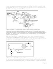
A first-pass design (Figure 1) gives good results, with the exception of the efficiency level at low VIN
and the high-voltage spikes on the Lx pin of IC1. These disadvantages can be countered with a better
Page 1 of 6