

下载

Maxim > Design Support > Technical Documents > Application Notes > Power-Supply Circuits > APP 2100
Keywords: current-mode DC-DC converter, 5V regulator, inverting switching regulator, AA cells
APPLICATION NOTE 2100
Inverter Circuit Derives 5V from Four AA Cells and
Simplifies Designs
Jul 09, 1998
Abstract: This design note shows a circuit that derives5V from four AA cells. A transformer enables an
inverting switching regulator, the MAX739, to generate -5V. Different connections are recommended if
the -5V supplies heavier load current.
Four AA cells in series—a common power source for portable instruments—produces a battery voltage
that declines from about 6V when fresh to about 4V when discharged. For 5V regulators, this above-and-
below variation complicates the circuit design.
Flyback-transformer circuits can convert 6V-to-4V inputs to a regulated 5V, as can a step-up (boost)
converter followed by a linear regulator. (For ±5V requirements, you can choose either circuit plus a
charge pump.) If, however, the instrument is fully portable and the battery voltage can float, a less
complicated inverter circuit can easily generate the 5V or ±5V rails. Moreover, the inverter's single
switching frequency simplifies filtering and precludes the generation of beat frequencies.
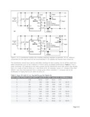
The inverter circuit substitutes a transformer with two matched windings for the usual inductor (Figure
1a). When IC1's internal switch turns off, the circuit impresses V
OUT
plus a diode drop across each
winding. With a proper choice of reference connection as shown, the second (right-hand) winding can
generate an additional supply voltage (-5V in this case).
V
OUT
(pin 8) is the feedback connection. For stability, the regulated output (5V in this case) should have
the heavier load. It usually does, because the negative rail in most systems is only a bias supply. But, if
your system demands more load current from the -5V output, you should reconnect the second winding
to produce the 5V output, as shown in Figure 1b.
Page 1 of 3