


下载

Maxim > Design Support > Technical Documents > Application Notes > High-Speed Interconnect > APP 4666
Keywords: key switch, key scan, switch matrix, controller, baseband, passive, conventional, power spectrum
density, PSD, electro magnetic interference, EMI, debounce, row, column, port
APPLICATION NOTE 4666
Using Key-Switch Controllers in Smartphones
By: Walter Chen, Principle Member of the Technical Staff, Applications
May 10, 2012
Abstract: This application note describes and compares two key-scan methods commonly used in
smartphone key pads. It shows the benefit of eliminating the use of EMI filters for the low EMI method. The
capacitive loading allowance associated with the ESD protection diode is also estimated.
Introduction
The brain of a smartphone is the baseband (BB) controller with built-in microprocessor and special-purpose
signal-processing circuits. Depending on the complexity of the BB controller, there are usually general-
purpose input/output (GPIO) pins available for key-switch implementation.
Most recently, special-purpose key-switch controller chips have been used in many smart cell phones. A
dedicated key-switch controller chip is used in a cell phone, sometimes because not enough GPIO pins are
available. This happens commonly when a BB controller designed for a feature phone is used for a
smartphone to avoid the system infrastructure redevelopment cost. At other times, it is used to minimize the
wires between the BB controller and the key pad. This is especially true for slide-out key pads where the
BB controller and the key pad are located on different PCBs or chassis. A key-switch controller is usually
connected to the BB controller by an I²C or SPI™ interface.
A dedicated switch controller can be implemented with an off-the-shelf GPIO chip or a small microcontroller
using the conventional key-scan method. A few dedicated special-purpose key-switch controller chips also
use the conventional key-scan method. In this article, the conventional and low-EMI key-scan methods are
compared to show the additional benefit of eliminating the use of EMI filters.
Conventional Key-Scan Method
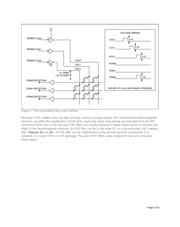
Figure 1 shows the general approach of the conventional key-scan method. This method applies both to
the BB controller's "GPIO pins" implementation and to some dedicated key-switch controllers. Some GPIO
pins are used as column output ports to drive the switch matrix; other GPIO pins are used as row input
ports to detect the contact of switches. There is usually no voltage applied to any key switches while they
are not being touched. Once a key is pressed, the key controller starts to scan all keys. The scanning is
carried out by raising the column voltages one at a time while checking, also one at a time, the input level
of each row. An 8 x 8 switch matrix can be scanned in 64 clock cycles. The clock frequency can range from
a few tens of kHz to a few MHz. Column output levels swing between logic low and high during the key
scan. The voltage can vary between 1.8V to 3.3V, depending on the key controller's power supply.
Page 1 of 8