
下载
Maxim > Design Support > Technical Documents > Application Notes > Automotive > APP 1057
Maxim > Design Support > Technical Documents > Application Notes > Temperature Sensors and Thermal Management > APP 1057
Keywords: temperature sensor, ideality, thermal diode, thermal sense diodes, temp sensor, remote temp
sensor, sensors, thermal, temperatuer, temperature
APPLICATION NOTE 1057
Compensating for Ideality Factor and Series
Resistance Differences between Thermal-Sense
Diodes
By: Kerry Lacanette
Sep 05, 2002
Abstract: When using an external thermal diode to measure temperature, the accuracy of the temperature
measurement depends on the characteristics of the external diode. Two critical parameters that affect
measurement accuracy are ideality factor and series resistance. This application note explains the effects of
these parameters on remote temperature-sensor measurements and discusses how to determine
compensation factors for their effects.
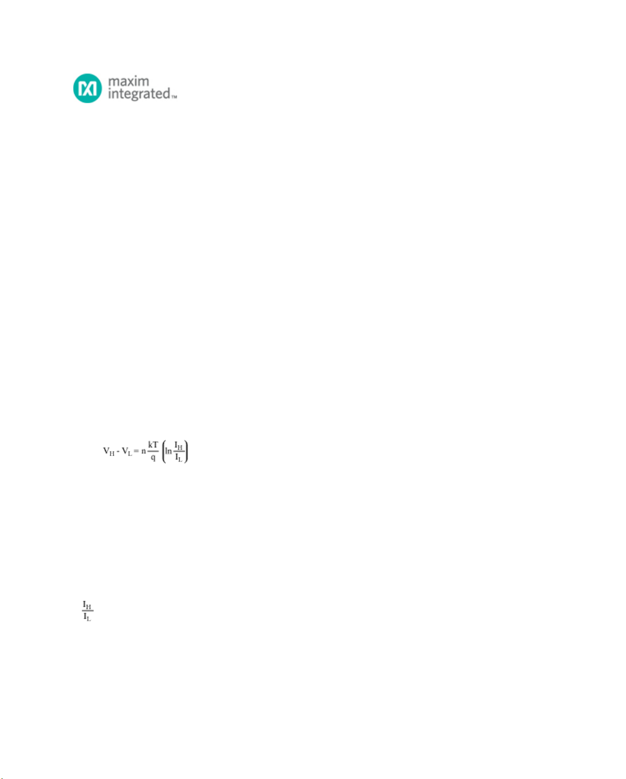
The most common approach to measuring temperature with a "remote-diode" temperature sensor is to force
two different currents through the diode¹, typically with a current ratio of about 10:1. The diode's voltage is
measured at each current level and the temperature is calculated based on the equation:
Where:
I
H
is the larger diode bias current.
I
L
is the smaller diode bias current.
V
H
is the diode voltage while IH is flowing.
V
L
is the diode voltage while IL is flowing.
n is the ideality factor of the diode (nominally 1, but varies with processing).
k is Boltzmann's constant (1.38 × 10
-23
joules/K).
T is the temperature in K.
q is the charge of an electron (1.60 × 10
-19
C)
If
= 10, this can be simplified to:
V
H
- V
L
= 1.986 × 10
-4
× πT
Ideality Factor Correction
Page 1 of 4